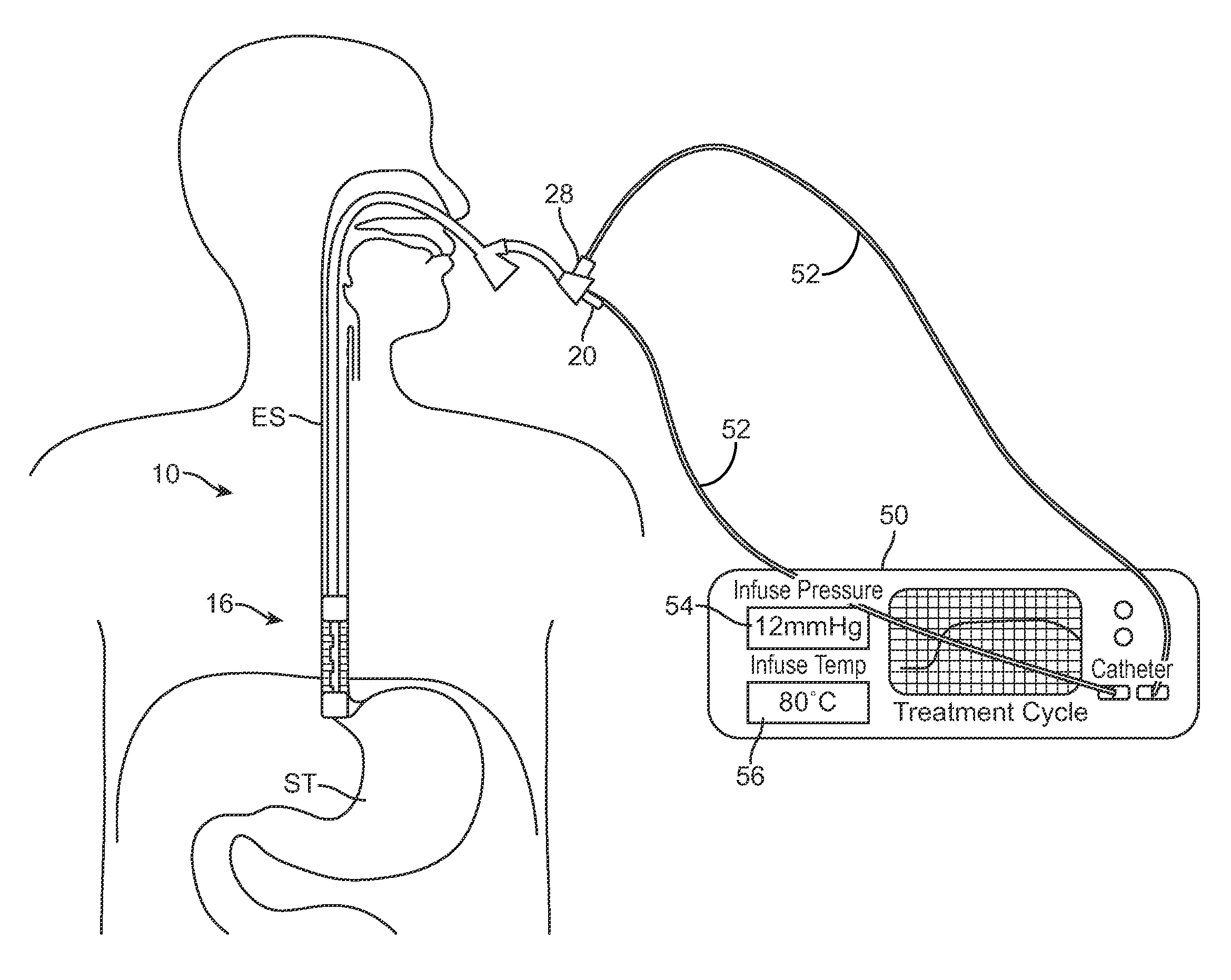
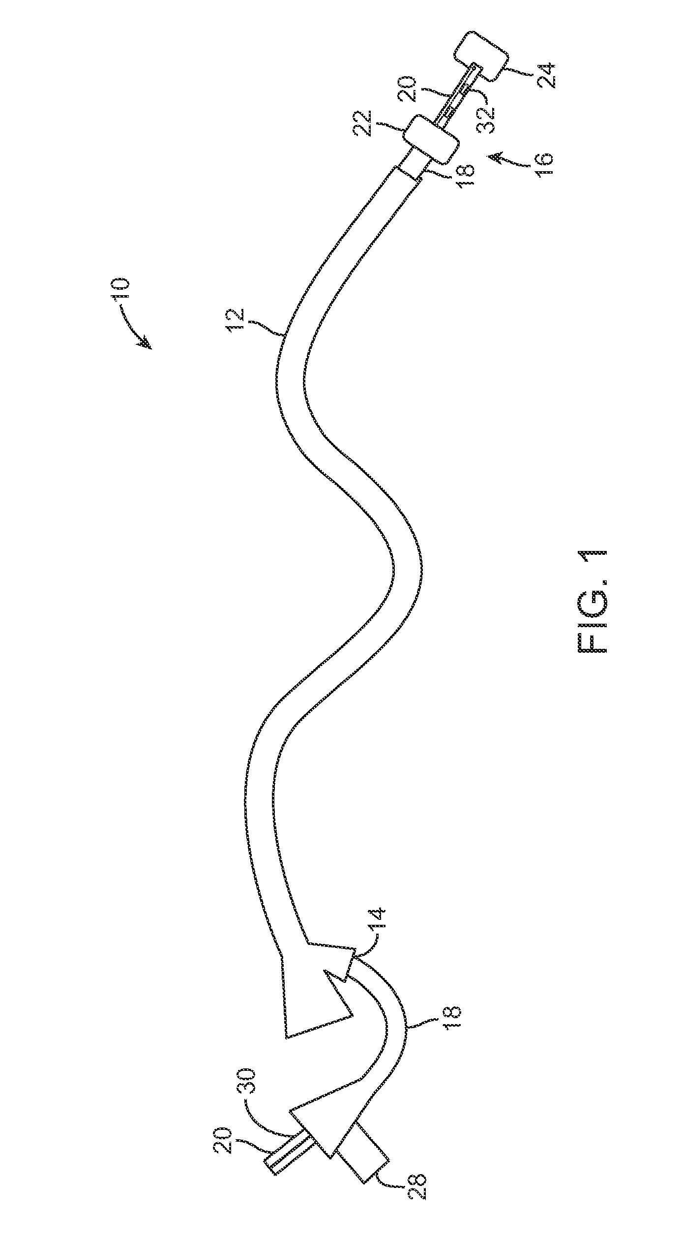
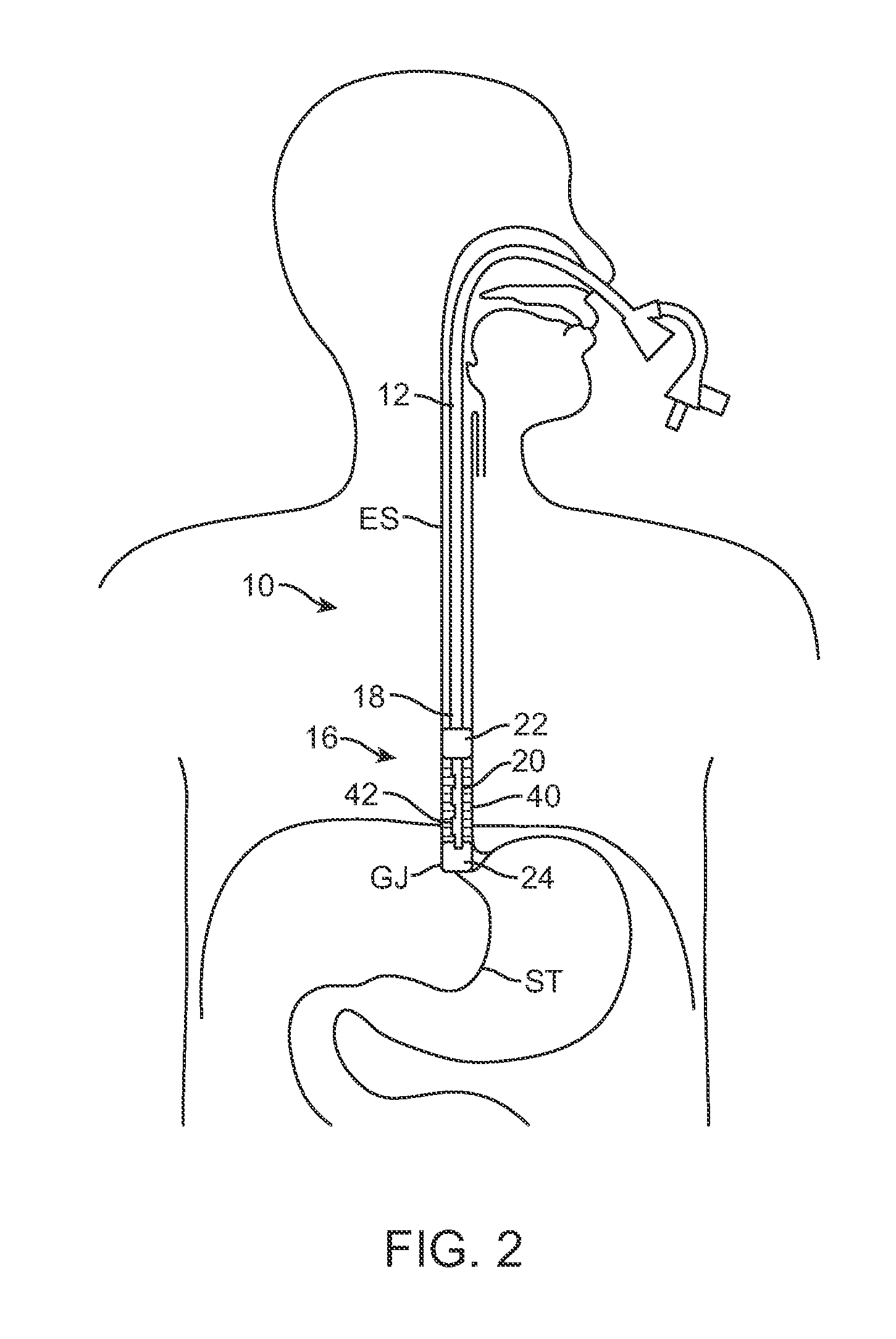
[0007]The catheter having the inflatable / expandable members and optional pressure or temperature-sensing elements may be fitted within the lumen of an
endoscope or other
visualization device allowing the therapy to be delivered under direct
visualization. In addition to direct visualization, this advance allows the scope to function as an insulator for the treatment catheter, thereby preventing unwanted
exposure of body cavities / lumens to the elevated temperatures found in the heated liquid and / or gas coursing within the treatment catheter.
[0010]Additionally, the
system may also incorporate features that may allow for efficacious therapy. For example, the
system may utilize a sub-zero degrees Celsius temperature fluid lavage. This cold lavage may allow for much better control than
charring and heating of the tissue and instead may provide a consistent depth of
ablation in a manner that allows for rapid
recovery and minimal post-operative pain (as opposed to heating methods). In addition, by using lavage of a liquid rather than cryogenic sprays (e.g., sprays which rely on the judgment of the user for determining time of spray application or spray location, etc.), the potential for over-
ablation may be avoided. Also, the relatively colder cryogenic sprays have been found, in many cases, to result in damage to the
endoscope while the higher temperatures possible with the
system described herein (e.g., anywhere from −5 degrees Celsius to −90 degrees Celsius) is much less likely to damage the delivery equipment.
[0013]In using a hypothermic liquid rather than a gas, a greater
thermal load can be repeatedly extracted from the tissue under controlled physiologic conditions using a liquid beyond the
thermal load which may be extracted using a compressed gas. A liquid lavage, on the other hand, may be controlled based on
temperature and pressure to provide a repeatable effect on the
target organ. Compressed gas or other rapid cooling mechanisms, though, may be utilized in combination with this therapy in order to chill a solution to subzero temperatures after introduction into the body. In this variation, the biocompatible liquid capable of retaining liquid characteristics in a subzero state, or “anti-freeze solution”, may be infused into the lumen or cavity after which the cooling probe may be introduced. Heat may be drawn from the anti-freeze solution until the desired hypothermic ablation temperature has been achieved for the desired duration of time. Fluid may or may not be circulated during this process via a pump or agitating element within the catheter in order to improve distribution of the ablative fluid.
[0014]In yet another variation, the treatment fluid may function to expand the
uterus for consistent ablation, function to distribute the cryoablative freezing more evenly throughout the
uterus, and potentially function to slow or prevent
ice formation at the surface of the lumen or
body cavity. The apparatus may be used with, for example, lipophilic, hydrophilic or amphipathic solutions with the latter two being having the ability to remove any aqueous fluid from the surface of the target cavity or lumen which may interfere with conduction of the heat from the target tissues into the cryoablative fluid.
[0027]Aside from the
balloon itself and the use of balloons for obstructing the os, internal os, and / or
external os, balloons or inflatable liners may also be used to insulate the cryogenic fluid during delivery into the
balloon to protect the surrounding tissue structures which are not to be ablated, such as the
cervix.


