Planar light source device, method for manufacturing the same, and display device having the same

a technology of light source device and display device, which is applied in the direction of girders, lighting and heating apparatus, instruments, etc., can solve the problems of increased overall thickness of the planar light source device, reduced light efficiency, and reduced uniformity of luminance,

Inactive Publication Date: 2005-11-17
SAMSUNG ELECTRONICS CO LTD
View PDF0 Cites 7 Cited by
  • Summary
  • Abstract
  • Description
  • Claims
  • Application Information

AI Technical Summary

Benefits of technology

[0005] The present invention provides a planar light source device having a planar a light source body comprising multiple discharging regions and at least one opening portion for air exhaust and injection of gases to be discharged; at least one affixing member being affixed to the light source body and seals the at least one opening portion; at least one getter being on the at least one affixing member and corresponds to the at least one opening portion; and first and second electrodes being formed on opposing edges defining the outer surface of the light source body.

Problems solved by technology

The two types of the cold cathode fluorescent lamps have some problems in that light efficiency is reduced by multiple optical members, such as a light guide plate or a diffusing plate, etc., and uniformity of luminance is reduced by complicated structures.
However, this results in some problems in that the overall thickness of the planar light source device is increased as a result of remaining marks of the exhaust tube and yield of the product is reduced by frequent damages in manufacturing processes.

Method used


Image

  • Planar light source device, method for manufacturing the same, and display device having the same
  • Planar light source device, method for manufacturing the same, and display device having the same
  • Planar light source device, method for manufacturing the same, and display device having the same

Examples


Embodiment Construction

[0020] Hereinafter the embodiments of the present invention will be described in detail with reference to the accompanying drawings.

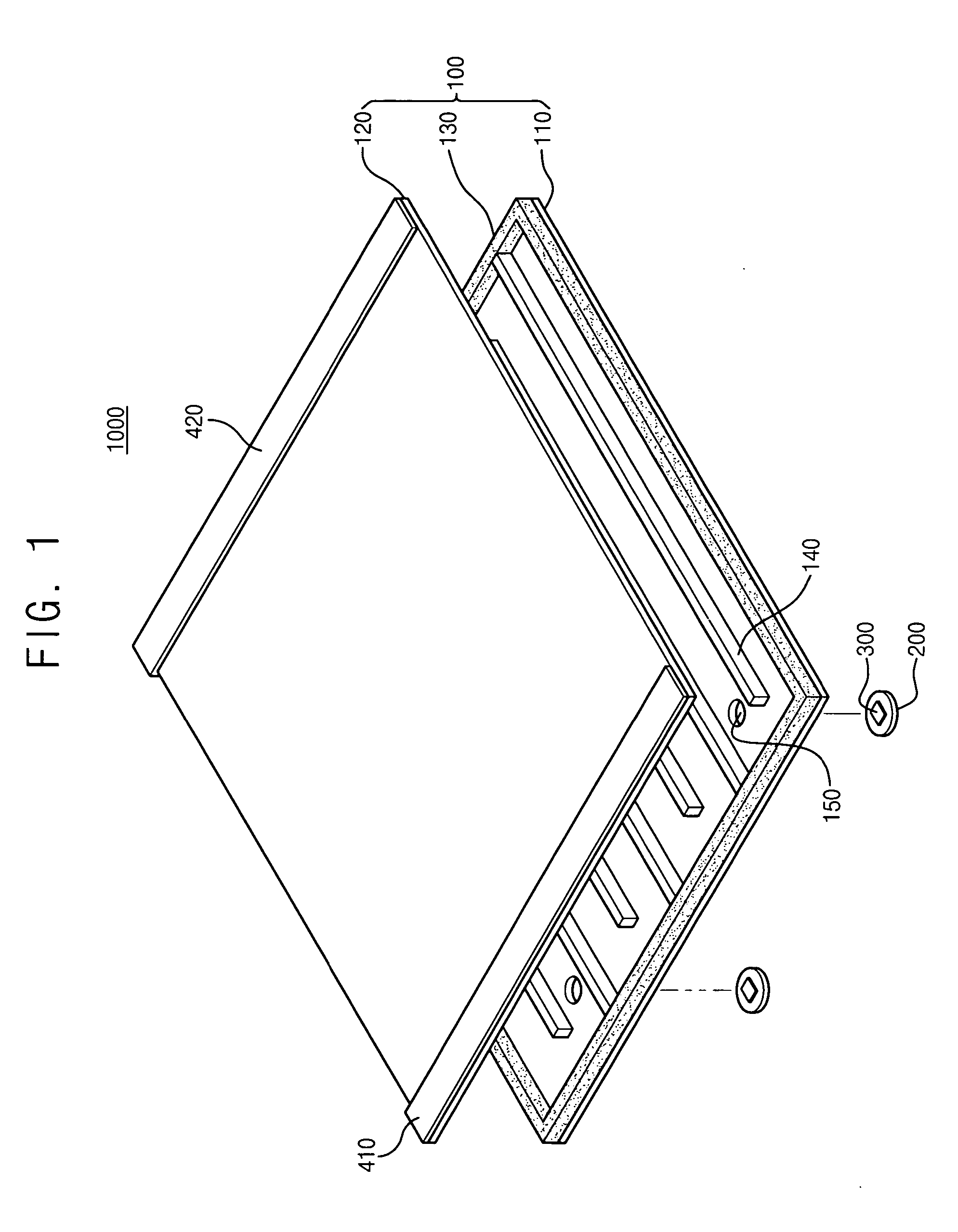
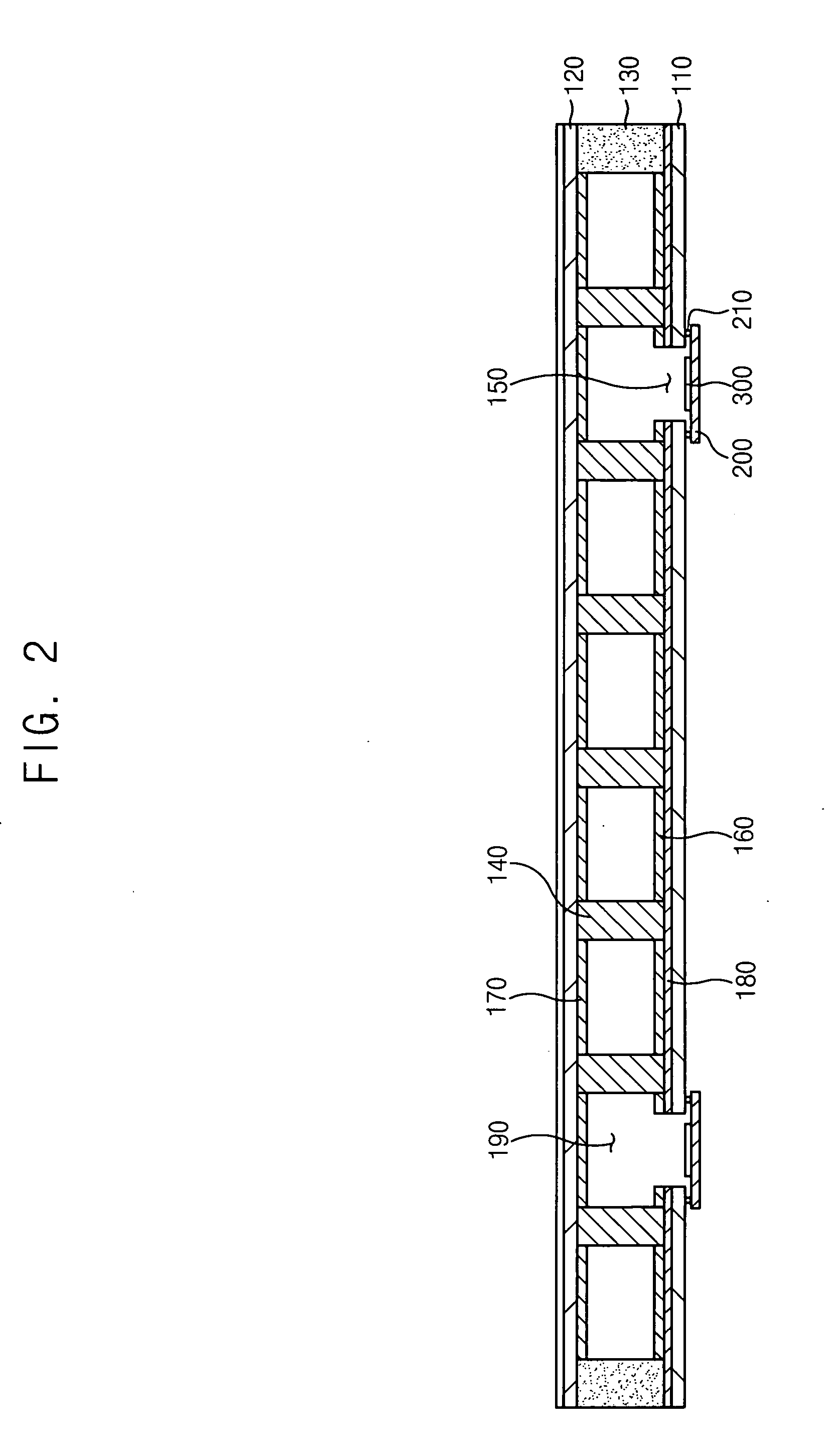
[0021]FIG. 1 is a perspective view of a planar light source device according to an exemplary embodiment, and FIG. 2 is a cross-sectional view of the planar light source device of FIG. 1.

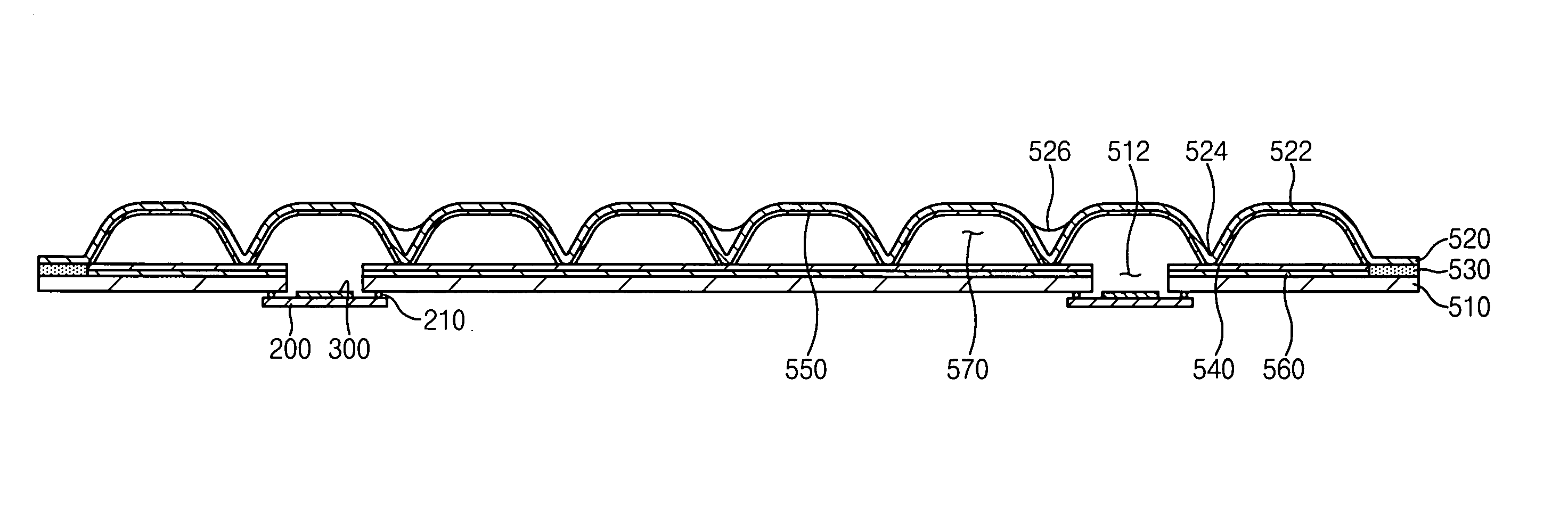
[0022] Referring to FIGS. 1 and 2, the planar light source device 1000 comprises a light source body 100, multiple affixing members 200 (just two shown), and multiple getters 300 (just two shown). The light source body 100 has multiple discharging regions 190 and multiple opening portions 150 (just two shown) for exhausting air inside of the light source body 100 and injecting gases to be discharged. In other words, the light source body 100 comprises a first substrate 110, a second substrate 120 facing the first substrate 110, and a sealing member 130 therebetween coupling the first substrate 110 with the second substrate 120. The first and second substrates 110 and 1...


PUM

PropertyMeasurementUnit
frequencyaaaaaaaaaa
frequencyaaaaaaaaaa
melting pointaaaaaaaaaa

Abstract

A display device comprises a planar light source device comprising a light source body having multiple opening portions for air exhaust and injection of the discharging gases, at least one affixing member being affixed to the light source body and sealing each of the multiple opening portions, at least one getter being on the at least one affixing member and corresponding to each of the multiple opening portions, and first and second electrodes being formed on opposing edges defining the outer surface of the light source body, a display unit displaying images using light from the planar light source device, and an inverter applying discharging voltages to the first and second electrodes for driving the planar light source device. According to this configuration, the present invention may reduce the thickness of the planar light source device and improve getting efficiency of the impurities and emitting efficiency of mercury by increasing the surface area of the getter.

Description

BACKGROUND OF THE INVENTION [0001] 1. Field of the Invention [0002] The present invention relates to a planar light source device, a method for manufacturing the same, and a display device having the same, and more particularly, to a planar light source device having no exhaust tube for exhausting air from inside of the planar light source and for injecting gases to be discharged, a method for manufacturing the same, and a display device having the same. [0003] 2. Description of the Related Art [0004] Generally, a cold cathode fluorescent lamp (CCFL) is used as a backlight assembly for a display device. Two types of the cold cathode fluorescent lamps include edge light and direct light types depending on the location of a light source, for example. The two types of the cold cathode fluorescent lamps have some problems in that light efficiency is reduced by multiple optical members, such as a light guide plate or a diffusing plate, etc., and uniformity of luminance is reduced by comp...

Claims


Application Information

Patent Timeline
Patent Type & Authority Applications(United States)
IPC IPC(8): F21S2/00F21Y105/00H01J7/18G02F1/13357H01J9/395H01J9/40H01J17/00H01J61/00H01J61/26H01J61/30H01J65/00H01J65/04
CPCG02F1/133604H01J7/186H01J9/395H01J65/046H01J61/26H01J61/307H01J9/40E04C3/07E04C2003/0421
Inventor PARK, HAE-IIHWANG, IN-SUNLEE, SANG-YUBYUN, JIN-SEOB
Owner SAMSUNG ELECTRONICS CO LTD
Why Eureka
Try Eureka