Sequence and timing control of writing and rewriting pixel memories for achieving higher number of gray scales

a technology of pixel memory and pixel memory, which is applied in the direction of color television details, television systems, instruments, etc., can solve the problems of limitation and difficulty in providing high-quality image display, adverse effects on image quality, and limitation of display quality, so as to achieve more flexible control of gray scales of display and low operating voltage

Active Publication Date: 2005-11-17
IGNITE INC
View PDF7 Cites 48 Cited by
  • Summary
  • Abstract
  • Description
  • Claims
  • Application Information

AI Technical Summary

Benefits of technology

[0012] The present invention relates to control circuits for micromirror devices and arrays of micromirror devices. The purpose of controlling the arrays is to apply such array as spatial light modulators (SLMs). In one aspect, the present invention provides a micromirror device in which the reflecting element is controlled to reflect light for image display at multiple intermediate positions for providing more flexibly controllable gray scales of display without requiring a higher speed of micromirror oscillation thus maintaining a low operational voltage.
[0014] In yet another aspect, the present invention provides a micromirror device comprising an array of micromirrors that are controlled to operate with intermediate oscillating states to provide a least brightness that is a fraction, e.g., approximately 37%, of the fully ON state. The gray scale for display is now controllable to project finer scale of brightness differences between adjacent pixels with an additional controllable state to provide a fraction of brightness of the fully-on state for display. The annoying artifacts shown on a display caused by adjacent pixels having huge gray scale gaps can be significantly reduced.

Problems solved by technology

Even though there are significant advances made in recent years on the technologies of implementing electromechanical micromirror devices as spatial light modulator, there are still limitations and difficulties when employed to provide high quality images display.
Specifically, when the display images are digitally controlled, the image qualities are adversely affected due to the fact that the image is not displayed with sufficient number of gray scales.
The on-and-off states of micromirror control scheme as that implemented in the U.S. Pat. No. 5,214,420 and by most of the conventional display system imposes a limitation on the quality of the display.
Specifically, when applying conventional configuration of control circuit has a limitation that the gray scale of conventional system (PWM between ON and OFF states) is limited by the LSB (least significant bit, or the least pulse width).
Due to the On-Off states implemented in the conventional systems, there is no way to provide shorter pulse width than LSB.
The limited gray scales lead to degradations of image display.
That leads to image degradations.
The artifacts are generated due to a technical limitation that the digital controlled display does not provide sufficient gray scales.
The micromirrors manufacture by applying the CMOS technologies probably would not be suitable for operation at such higher range of voltages and therefore the DMOS micromirror devices may be required.
In order to achieve higher degree of gray scale control, a more complicate manufacturing process and larger device areas are necessary when DMOS micromirror is implemented.
Conventional modes of micromirror control are therefore facing a technical challenge that the gray scale accuracy has to be sacrificed for the benefits of smaller and more cost effective micromirror display due to the operational voltage limitations.
However, these inventions have not addressed and provided direct resolutions for a person of ordinary skill in the art to overcome the above-discussed limitations and difficulties.

Method used


Image

  • Sequence and timing control of writing and rewriting pixel memories for achieving higher number of gray scales
  • Sequence and timing control of writing and rewriting pixel memories for achieving higher number of gray scales
  • Sequence and timing control of writing and rewriting pixel memories for achieving higher number of gray scales

Examples


Embodiment Construction

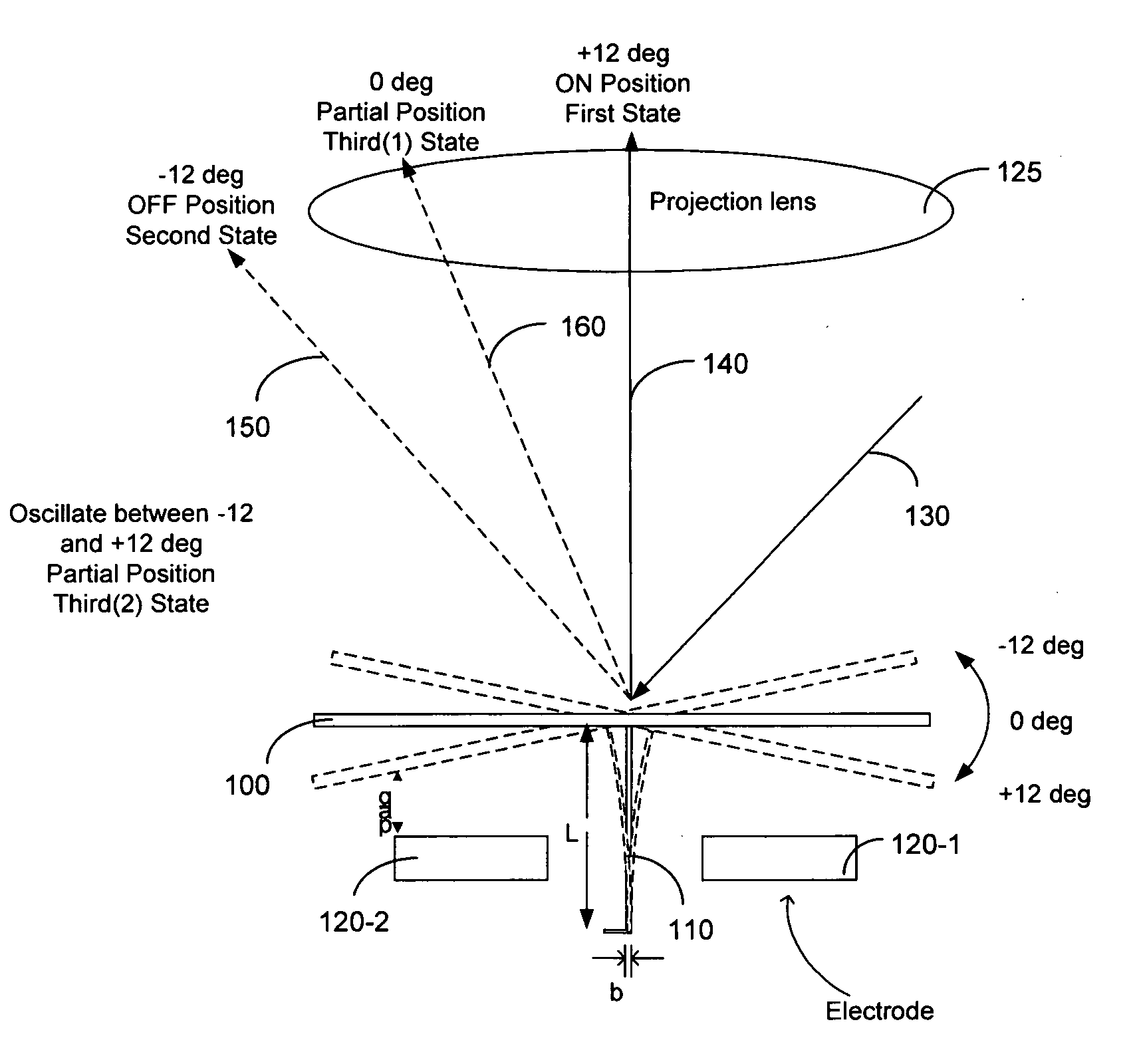
[0030] Referring to FIG. 2 for a side cross sectional view for illustrating the oscillating motions of a micromirrors according to the control circuit of the present invention. A micromirror 100 supported on a hinge 110 formed on a substrate (not shown), is electrically controlled by two electrodes 120-1 and 120-2 to move to different positions, e.g., from +12 degrees to −12 degrees as shown. The incident light is projected along an optical path 130 and the light reflected from the micromirror 100 is projected to a projection lens 125 for further projecting to a display surface (not shown). The micromirror is controlled to move to a full-on state when the micromirror is positioned at the +12 degrees with the reflected light projected fully onto the projection lens along a 140 direction perpendicular to the projection lens 125. The micromirror 100 is controlled to move to a full-off state when the micromirror 100 is positioned at a −12 degrees with the reflected light 150 totally mis...


PUM


Abstract

A micromirror device with a lower driving voltage is disclosed. The lower driving voltage is achieved by projecting a partial light for image display during a micromirror is oscillating from fully on state to a fully off state. The micromirror device includes a reflective element supported on a hinge for oscillating and positioning at least three states. These three states are a fully on state, a fully off state, and a partially ON angular positions in responding to a digital control signal. The oscillation of the micromirrors is controlled in responding to a digital control signal wherein the digital control signal is controlled for writing into display pixels in an interleave-and-jump sequence to jump multiple lines to non-sequential lines of a display image.

Description

[0001] This application is a Continuation in Part (CIP) Application of pending U.S. patent applications Ser. Nos. 10 / 698,620 filed on Nov. 1, 2003, 10 / 699,140 filed on Nov. 1, 2003, and 10 / 699,143 filed on Nov. 1, 2003 by the Applicant of this Patent Applications. The disclosures made in these Patent Applications are hereby incorporated by reference in this Patent Application.TECHNICAL FIELD [0002] This invention relates to micromirror arrays and control circuits to control the micromirrors. More particularly, this invention relates to signal control methods for controlling the sequential order and timing of inputting intermediate state signals when scanning through a display frame of horizontal lines to enable more accurate control of gray scales while operated with low driving voltages. BACKGROUND ART [0003] Even though there are significant advances made in recent years on the technologies of implementing electromechanical micromirror devices as spatial light modulator, there are...

Claims


Application Information

Patent Timeline
Patent Type & Authority Applications(United States)
IPC IPC(8): G02B26/00G02B26/08G09G3/20G09G3/34H04N5/74
CPCG02B26/0841G09G3/2011G09G3/2037G09G3/2077G09G3/346H04N2005/7466G09G2300/0852G09G2310/02G09G2310/0251G09G2310/0262H04N5/7458G09G2300/0842
Inventor ISHII, FUSAO
Owner IGNITE INC
Why Eureka
Try Eureka