Disposable paint cup
- Summary
- Abstract
- Description
- Claims
- Application Information
AI Technical Summary
Benefits of technology
Problems solved by technology
Method used
Image

Examples
Embodiment Construction
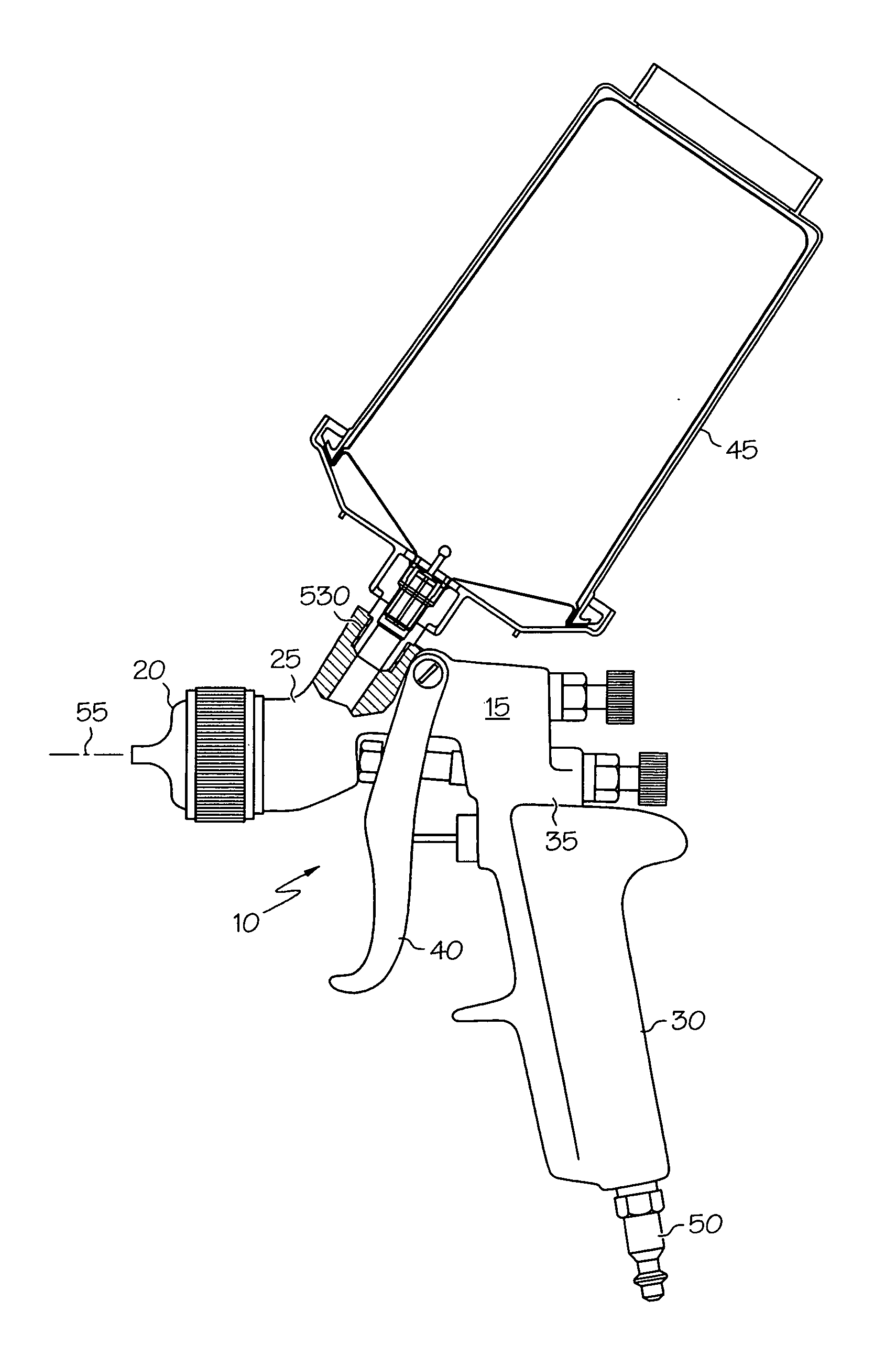
[0023] A fluid supply assembly attached to a fluid applicator is shown in FIG. 1. In one embodiment, the fluid supply assembly is for feeding liquid, such as paint, to the fluid applicator, such as a paint sprayer. The present invention will be described for a paint sprayer, such as a gravity feed paint sprayer for use in applying paint to coat substrate surfaces. The paint sprayer can be used in the automotive refinishing market, such as automobile body shops, for repainting automobiles. Although the fluid supply assembly is described for a paint sprayer, it is not limited to such use. It can be used for supplying other flowable liquids, including, but not limited to, beverages, foods, condiments (such as ketchup), gasoline, petrochemicals and hydrocarbons, water, water-based solutions, solvent-based solutions, emulsions, adhesives, and the like.
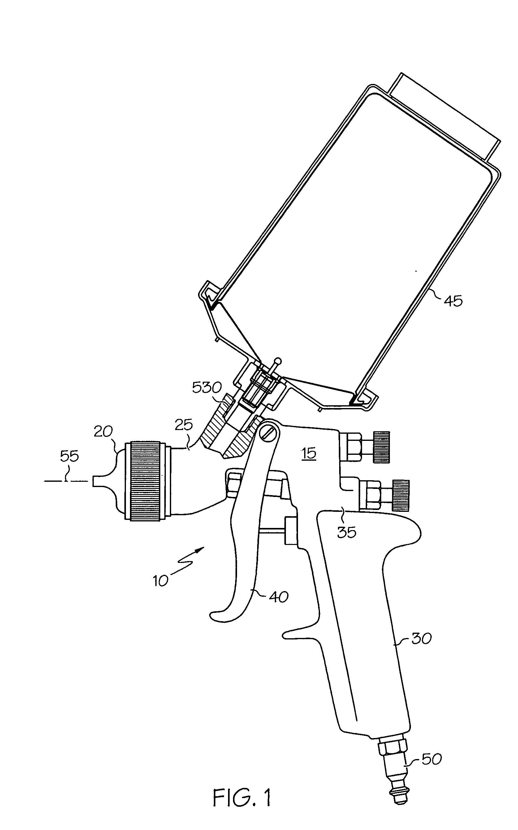
[0024] Referring to FIG. 1, a paint sprayer 10 is shown. It includes a body 15, a nozzle assembly 20 secured to a front end 25 of body 15...
PUM
 Abstract
Description
Claims
Application Information
 - Generate Ideas
- Intellectual Property
- Life Sciences
- Materials
- Tech Scout
- Unparalleled Data Quality
- Higher Quality Content
- 60% Fewer Hallucinations
Browse by: Latest US Patents, China's latest patents, Technical Efficacy Thesaurus, Application Domain, Technology Topic, Popular Technical Reports.
© 2025 PatSnap. All rights reserved.Legal|Privacy policy|Modern Slavery Act Transparency Statement|Sitemap|About US| Contact US: help@patsnap.com