Electrical current measurement in a fuel cell

a fuel cell and electric current technology, applied in the field of fuel cell power systems, can solve the problems of significant drift, affecting the electrical current sensor, and not working, and achieve the effects of low cost, low cost, and cost saving

Inactive Publication Date: 2005-11-24
GM GLOBAL TECH OPERATIONS LLC +1
View PDF11 Cites 18 Cited by
  • Summary
  • Abstract
  • Description
  • Claims
  • Application Information

AI Technical Summary

Benefits of technology

[0017] The present invention may provide cost savings from the use of “low cost” electrical current sensors in a fuel cell system even though such “low cost” sensors have less rigorous accuracy and reliability attributes than “high cost” electrical current sensors; reliable fuel cell operation from combining electrical current measurements into a composite measurement for control; fuel cell system diagnostics; minimized shutdowns of otherwise trusted sensors and efficient fuel cell performance as drifting sensors are isolated and excluded from inducing inappropriate manipulations to fuel cell stack loading.

Problems solved by technology

One disadvantage, however, in using such an averaged electrical current measurement directly is that such an approach does not account for failure in a particular electrical current sensor.
In this regard, a common failure mode for a Hall-effect electrical current sensor is that significant drift will occur which is not readily detected using common sensor fault detection methods such as short circuit analysis, open wire detection, sensor out of range evaluation, and the like.
Another disadvantage derives from unnecessary shutdown of the fuel cell stack set if a single sensor failure halts the entire stack set in an otherwise unnecessary shutdown.
One solution to minimizing unnecessary shutdowns is to use high cost electrical current sensors which provide high reliability; however, the high cost aspect of such a solution is not desirable in minimizing the cost for a fuel cell system.

Method used


Image

  • Electrical current measurement in a fuel cell
  • Electrical current measurement in a fuel cell
  • Electrical current measurement in a fuel cell

Examples


Embodiment Construction

[0027] The following description of the preferred embodiment is merely exemplary in nature and is in no way intended to limit the invention, its application, or uses.

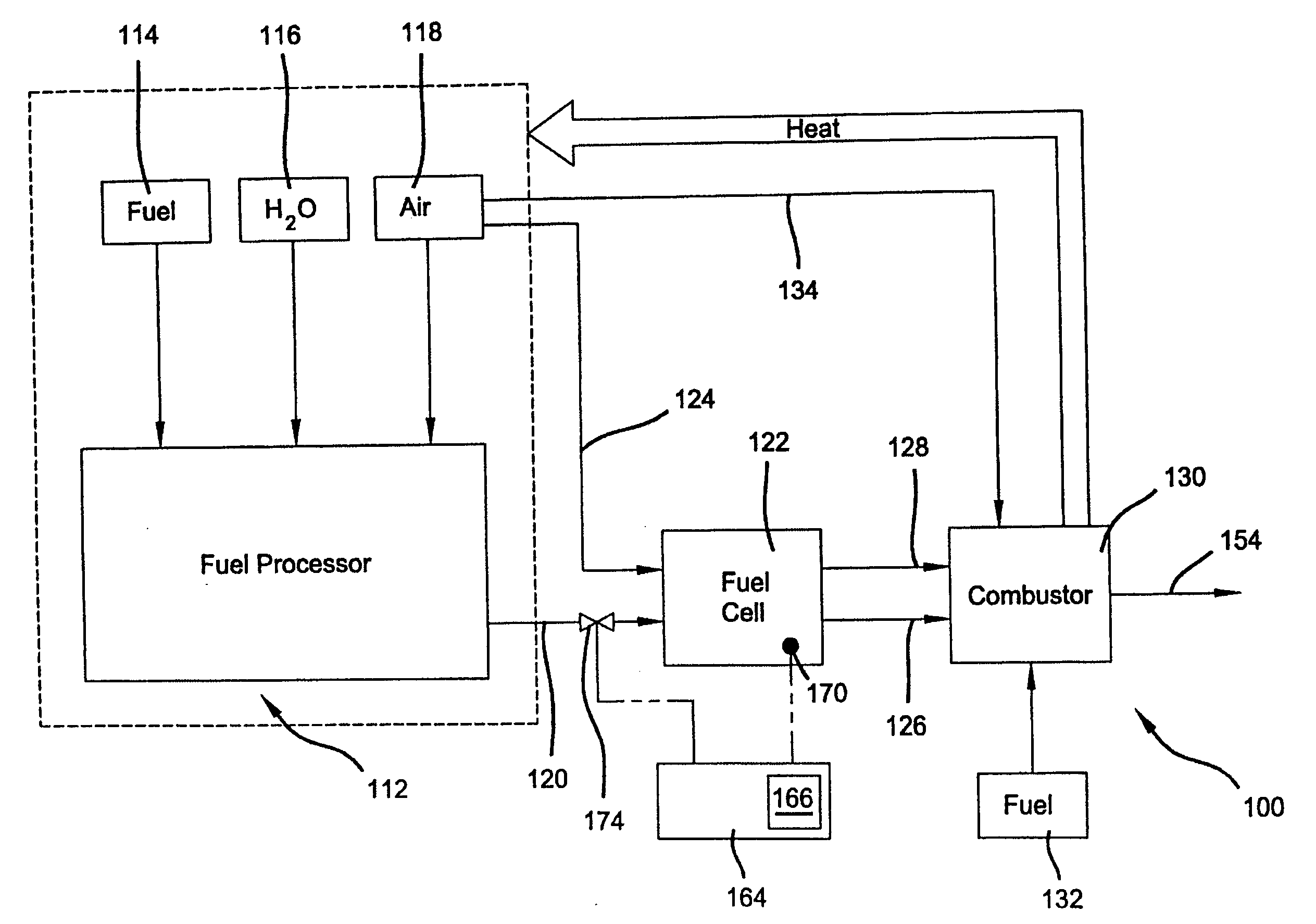
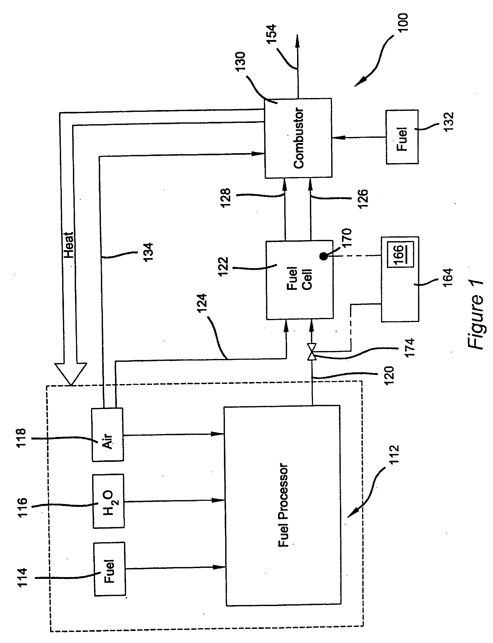
[0028] Real-time process control is generally implemented to control the fuel cell power system described herein. In this regard, real-time computer processing is broadly defined as a method of processing in which an event causes a given reaction within an actual time limit and wherein actions are specifically controlled within the context of and by external conditions and actual times. As an associated clarification in the realm of process control, real-time controlled processing relates to the performance of associated process control logical, decision, and quantitative operations intrinsic to a process control decision algorithm functioning as part of a controlled apparatus implementing a process (such as the fuel cell benefiting from the present invention) wherein the process control decision algorithm is periodica...


PUM

PropertyMeasurementUnit
poweraaaaaaaaaa
electrical currentaaaaaaaaaa
threshold rangeaaaaaaaaaa

Abstract

A plurality of electrical current sensors for a set of fuel cell stacks in series independently measure electrical current in a fuel cell, and an acceptability status is determined for each electrical current sensor by independent comparison of each sensor measurement to the individual values of the other sensor measurements. A characteristic current measurement is derived from all electrical current sensors having an acceptability status which is trustworthy.

Description

CROSS-REFERENCE TO RELATED APPLICATIONS [0001] This application claims the benefit of U.S. Provisional Application No. 60 / 572,031, filed on May 18, 2004, the disclosure of which is incorporated herein by reference.FIELD OF THE INVENTION [0002] The present invention relates to fuel cell power systems and more particularly to methods for measuring electrical current generated by a fuel cell stack of the fuel cell power system. BACKGROUND OF THE INVENTION [0003] Conventional fuel cell power systems convert a fuel and an oxidant to electricity in a fuel cell stack. A typical fuel cell stack includes a proton exchange membrane (“PEM”) with a catalytic anode layer and a catalytic cathode layer formed on opposite faces thereof. Reactant gases are directed across the catalytic faces to facilitate reaction of fuel (such as hydrogen) and oxidants (such as oxygen or air) in to electricity. [0004] Effective operation of a fuel cell stack or set of fuel cell stacks requires measurement of electr...

Claims


Application Information

Patent Timeline
Patent Type & Authority Applications(United States)
IPC IPC(8): H01M8/04H01M8/06H01M8/10H01M8/24
CPCH01M8/04014H01M8/04582H01M8/0618H01M8/0662Y02E60/50H01M8/242H01M8/249H01M2008/1095H01M8/2415H01M8/2484
Inventor LOGAN, VICTOR W.CLINGERMAN, BRUCE J.DANDALIDES, JAMES W.GONSER, SCOTT B.
Owner GM GLOBAL TECH OPERATIONS LLC
Why Eureka
Try Eureka