Low temperature clothes dryer

a clothes dryer and low temperature technology, applied in the field of clothes dryer cabinets, can solve the problems of evaporation of evaporator, stoppage of air circulation, and temperature increase of circulating air to a point above which clothing may be damaged,

Inactive Publication Date: 2005-12-22
MARUCA ROBERT E
View PDF1 Cites 63 Cited by
  • Summary
  • Abstract
  • Description
  • Claims
  • Application Information

AI Technical Summary

Benefits of technology

[0013] The low temperature clothes dryer of the present invention provides a movable cabinet, constructed of an insulative material, preferably wood, which includes a drying chamber, upper and lower airflow plenums, a dehumidifier, a duct connecting one plenum to the dehumidifier, and another duct connecting the dehumidifier with the other plenum, thereby forming a closed air circulation loop. The drying chamber provides for removable horizontal screens for supporting clothing items and a hanging bar for hanging clothes to be dried. A timing control allows setting the time of operation of the drying cabinet. An electric heater with thermostat is provided to initially raise and maintain the air temperature within the drying chamber to at least about 90 degrees F. and maintains it at at least that temperature. The dehumidifier is then operated, providing for circulation through the ducts and drying cabinet by an internal fan. The dehumidifier has an evaporator through which warm, humid air is passed, thereby cooling the air and condensing water therefrom, the water being collected in a removable container or drained through a drain hose to a sewer. The fan then forces the cooled, dried air through a condenser which heats the dried air for recirculation through the drying chamber by means of ducts, thereby drying the clothing therein.

Problems solved by technology

As the operation of the dryer proceeds, the temperature of the circulating air may increase to a point above which the clothing may be damaged.
Operation of the dehumidifier within the humid environment of the dryer below a temperature of 65 to 70 degrees F. may result in freezing up of the evaporator and stoppage of air circulation.

Method used


Image

  • Low temperature clothes dryer
  • Low temperature clothes dryer
  • Low temperature clothes dryer

Examples


Embodiment Construction

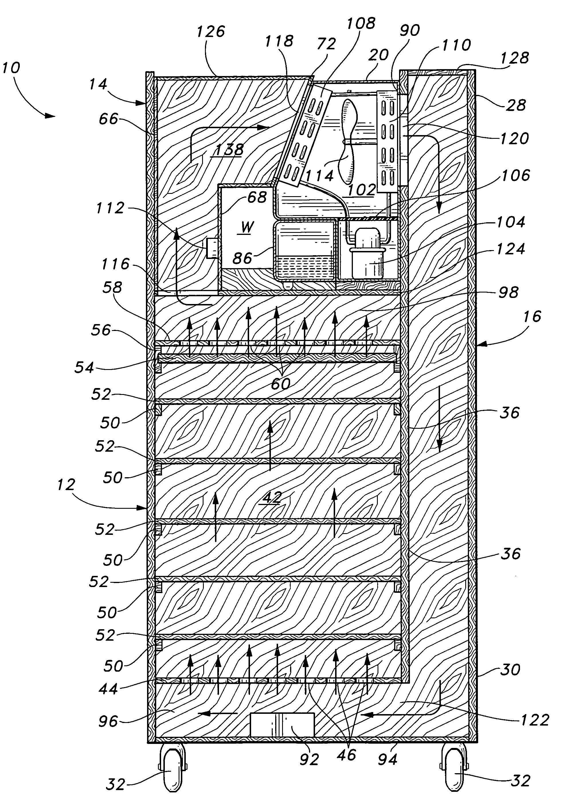
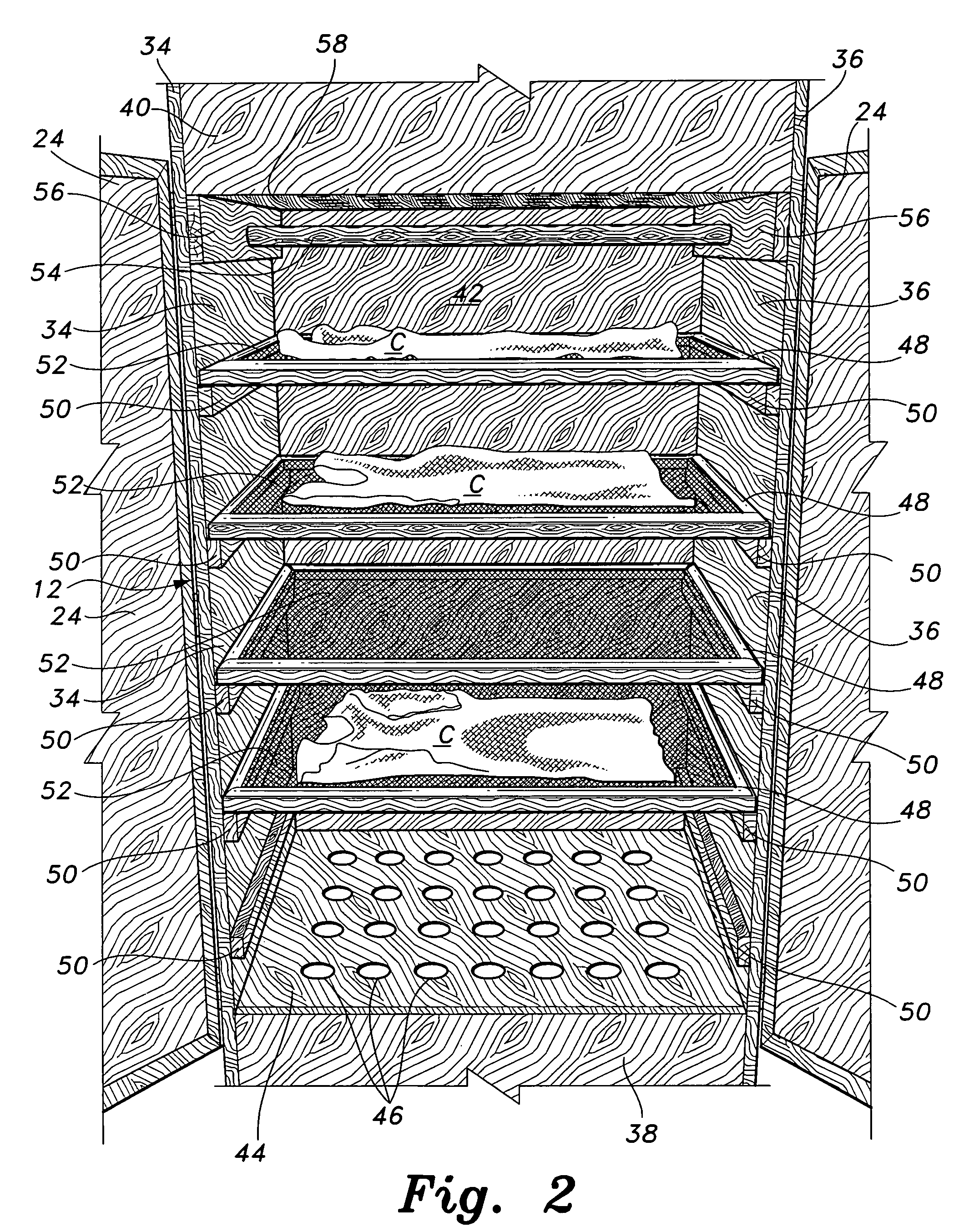
[0026] The present invention is a low temperature clothes dryer, having a movable cabinet, and which includes a drying chamber, upper and lower airflow plenums, a dehumidifier, a duct connecting one plenum to the dehumidifier, and another duct connecting the dehumidifier with the other plenum, thereby forming a closed air circulation loop. The drying chamber provides for removable horizontal screens for supporting clothing items, and a hanging bar for hanging clothes to be dried.

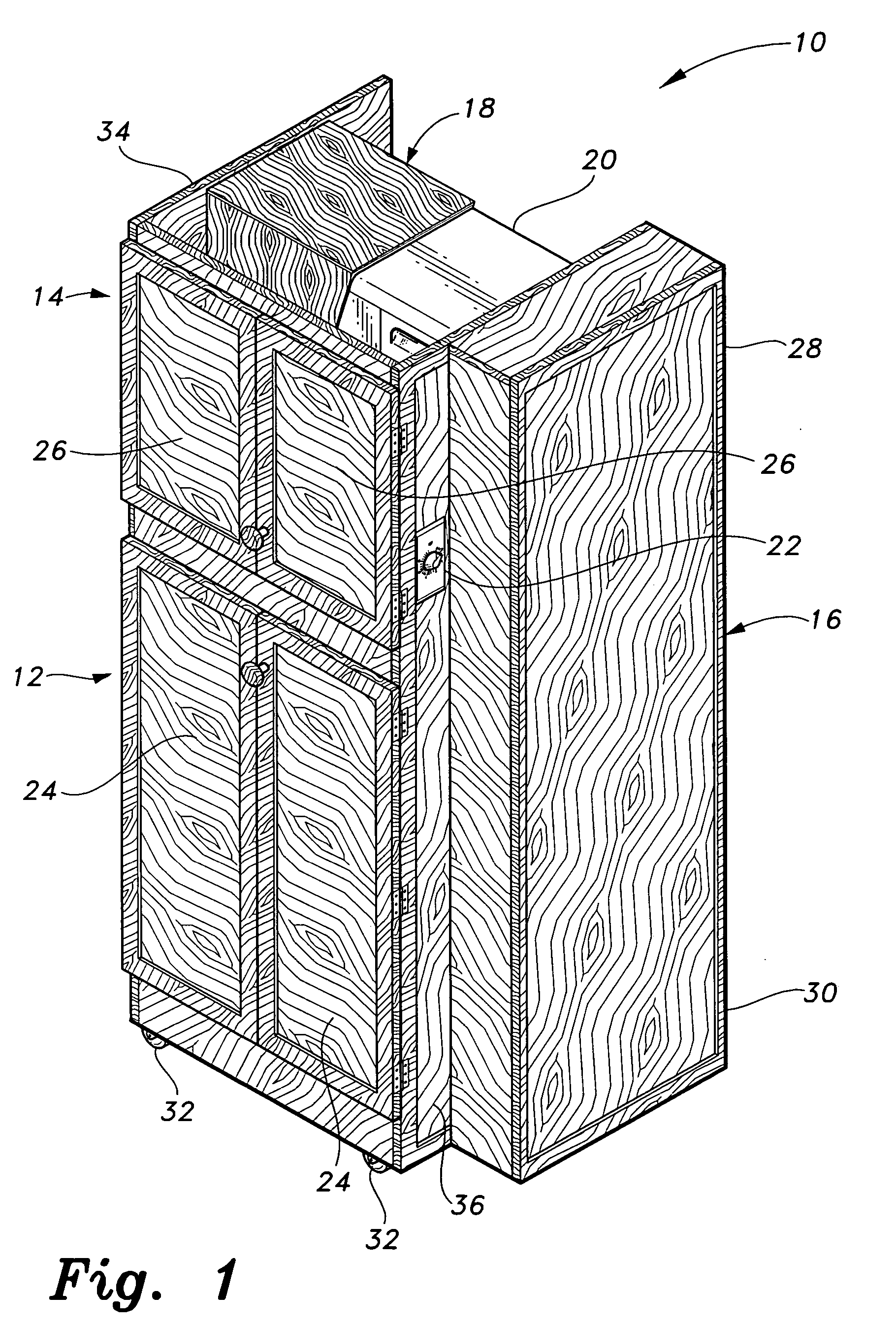
[0027] Referring to FIG. 1, there is shown a perspective view of the low temperature clothes drying system of the present invention referred to by the reference number 10. The system includes a drying chamber 12, a dehumidifying module enclosure 14, a recycle duct 16, a wet air return duct 18 and a dehumidifier unit 20. A timer control 22 mounted on the dehumidifying enclosure allows setting time for operation of the system 10. Drying chamber 12 has doors 24 for access to the drying cabinet for placement an...


PUM


Abstract

A low temperature clothes dryer having a drying chamber provides removable horizontal screens supporting clothing items and a hanging bar for hanging clothes to be dried. A timing control allows setting the time of operation of the drying cabinet. An electric heater with thermostat is provided to initially raise and maintain the air temperature within the drying chamber to at least about 90 degrees F. The dehumidifier is then operated, providing for circulation through the ducts and drying cabinet by an internal fan. The dehumidifier has an evaporator through which warm, humid air is passed, thereby cooling the air and condensing water therefrom, the water being collected in a removable container or drained through a drain hose. The fan forces the cooled, dried air through a condenser which heats the dried air for recirculation through the drying chamber by means of ducts, thereby drying the clothing therein.

Description

BACKGROUND OF THE INVENTION [0001] 1. Field of the Invention [0002] The present invention relates to low temperature evaporative clothes dryers. More particularly, the present invention relates to clothes drying cabinets employing circulating drying air from an air dehumidifier. [0003] 2. Description of the Related Art [0004] The use of cabinet type clothes dryers is well known, particularly for woolens and delicate items which are harmed by conventional tumble dryers. Also, in locations where energy is at a premium, cabinet dryers may be more energy efficient than conventional clothes dryers. In cabinet dryers the clothes are either hung as in clothes cabinets or laid flat on supports. Such dryers may simply circulate outside air through the cabinet in cases where the outside air is relatively dry. Heaters may also be used to heat the air supplied to the cabinet. In the most sophisticated embodiments, air is at least partially recirculated through the cabinet and a dehumidifier rem...

Claims


Application Information

Patent Timeline
Patent Type & Authority Applications(United States)
IPC IPC(8): D06F34/26D06F58/10D06F58/20F26B19/00
CPCD06F58/20D06F58/10D06F34/26
Inventor MARUCA, ROBERT E.
Owner MARUCA ROBERT E
Why Eureka
Try Eureka