
Dental floss tool device and method

Inactive Publication Date: 2005-12-08
MAJOR MARK L
View PDF14 Cites 3 Cited by
  • Summary
  • Abstract
  • Description
  • Claims
  • Application Information

AI Technical Summary

Benefits of technology

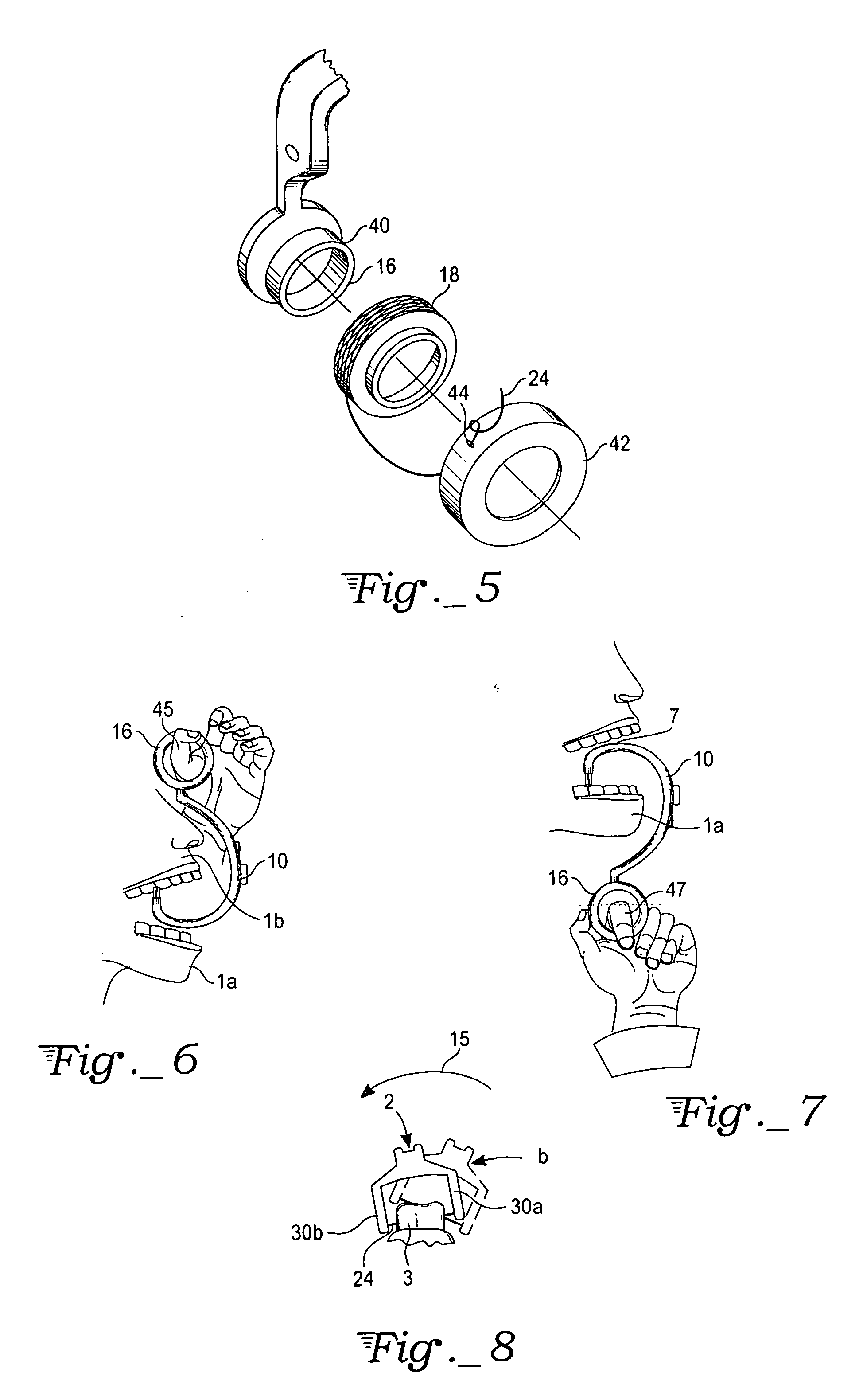
[0008] The present device includes a jaw hook body having a set of spaced dental floss holding projections at a first end and a grip handle at the second end of the jaw hook body. A floss retainer is positioned on the tool such that dental floss strung between the set of spaced dental floss holding projections may be secured on the floss retainer. This tool allows the user to grip the grip handle with one or more curled fingers and, using an essentially vertical motion, pull the floss between the teeth. This device may include a spool on the handle or in the body of the tool for holding a spool of dental floss. This spool retainer may have a cover protecting the dental floss from contamination. The body of the tool may also include a floss cutter located on the tool body. The grip handle may include specialized features, for example including a thumb grip or rubberized inner surface. Grooves along the body of the tool in the projections for holding the floss may aid in ensuring that the floss is retained in the tool. The method of using this tool includes applying a vertical (up and down) force above or below a user's jaw. The device may be rocked during use to facilitate the cleaning of the space between teeth. A bite surface on the tool's body may aid in applying the desired force. This pulling motion may be easier than the pushing motion required in prior devices.

Problems solved by technology

However, the use of dental floss may be difficult for some users.
This pushing may be awkward and cumbersome for some users.

Method used


Image

  • Dental floss tool device and method
  • Dental floss tool device and method
  • Dental floss tool device and method

Examples


Embodiment Construction

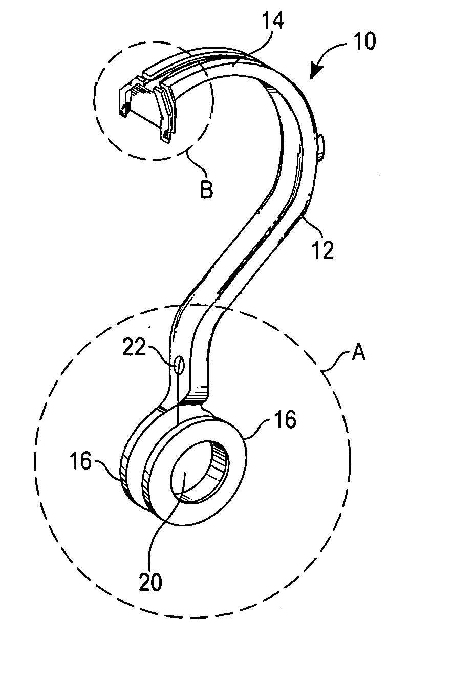
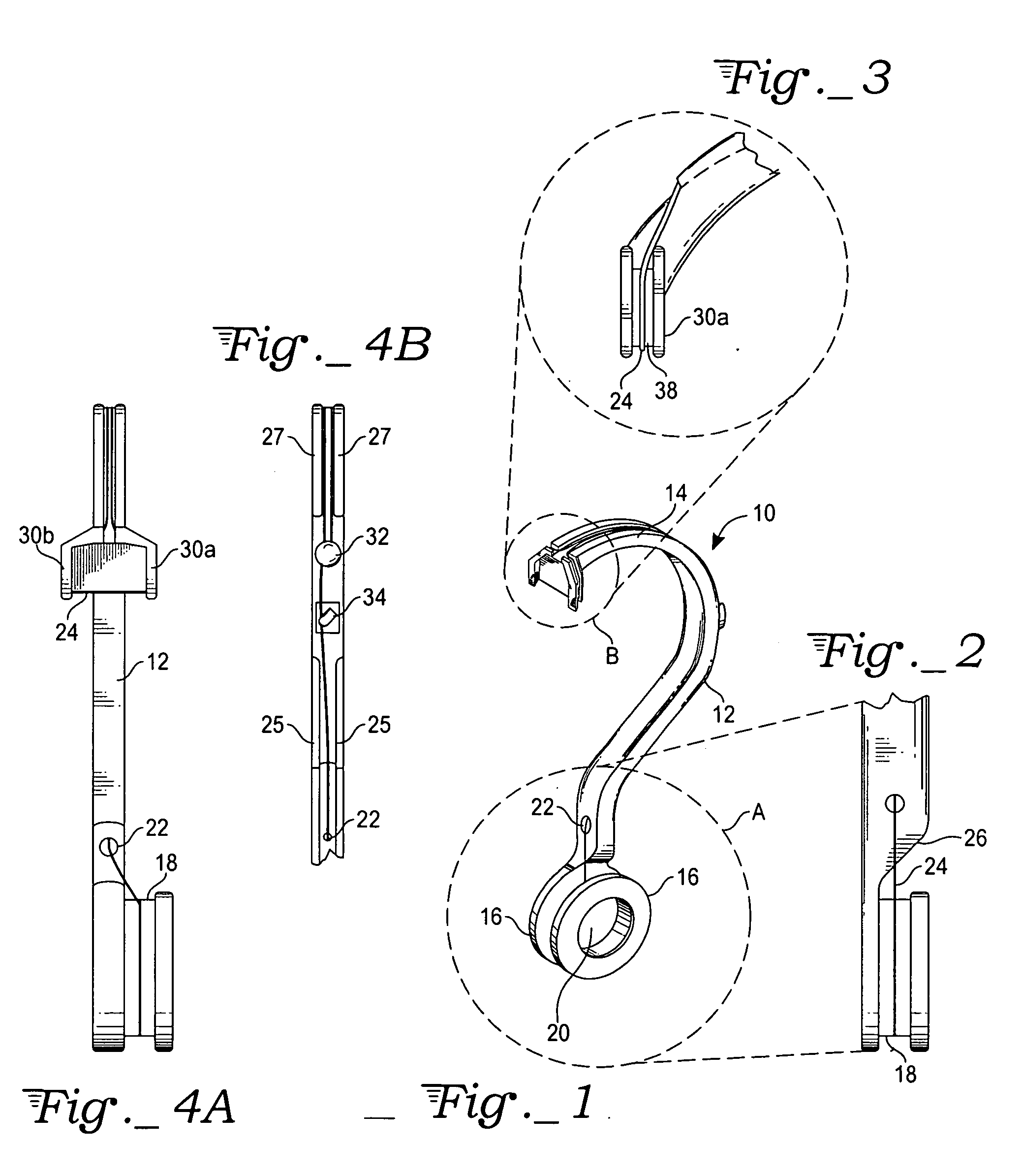
[0024] With reference to FIG. 1, the dental floss tool 10 is shown including a tool body 12 having a top section 14 at one end of the tool body 12 and a handle 16 at an opposite end of the tool body 12. The curved, generally half-circular shape of the tool body 12 allows a user to insert the tool into the user's mouth. Floss secured between projections at one end of the tool body 12 is able to reach even the back teeth in the user's mouth. This shape is referred to as a “jaw hook body”. This body generally has a question mark shape.

[0025] The handle 16 includes a through hole 20 through which a user can place one or more fingers. In this embodiment, a spool of dental floss 18 may be mounted on handle 16. As show in FIG. 2, spool 18 holds floss 24. A recessed surface 26 allows simplified access to floss spools at this location. Returning to FIG. 1, the floss fed from spool 18 is fed through hole 22 on the tool body.

[0026] With reference to FIG. 3, the head of the tool, detail B fro...


PUM


Abstract

A device to aid in flossing teeth including a jaw hook body, a pair of floss retaining projections on one end of the jaw hook body, and a grip handle at an opposite end of the jaw hook body. The grip handle may be a closed loop, an open loop, a padded structure, a pivoting structure, a decorative structure, a structure for holding the tool upright on a surface, or some combination of these features.

Description

CROSS-REFERENCE TO RELATED APPLICATIONS [0001] The application claims priority from U.S. provisional applications Ser. No. 60 / 576,538, filed Jun. 2, 2004, and Ser. No. 60 / 585,244, filed Jul. 2, 2004.TECHNICAL FIELD [0002] The present device relates to a device and method for using dental floss. BACKGROUND ART [0003] Flossing between teeth is recommended for proper dental hygiene. However, the use of dental floss may be difficult for some users. This problem is enhanced for users with poor finger dexterity, users who are missing fingers, or users that have had other hand disabilities. [0004] A number of prior devices have been created to aid in flossing. For example, U.S. Pat. No. 3,858,594 discloses a dental floss holder that dispenses floss through a hole in the main body of the device. A cavity within the body of the device holds a spool, which dispenses floss to this hole. The body has a curved shape terminating in a pair of forked tines extending from the device body and spaced ...

Claims


Application Information

Patent Timeline
IPC IPC(8): A45D24/00A61C15/00A61C15/04
CPCA61C15/046A61C15/043
Inventor MAJOR, MARK L.
Owner MAJOR MARK L
Learn More