
Methods, systems and controllers for facilitating cleaning of an imaging element of an imaging device

Active Publication Date: 2021-08-24
CLEARCAM INC +1
View PDF43 Cites 0 Cited by
  • Summary
  • Abstract
  • Description
  • Claims
  • Application Information

AI Technical Summary

Benefits of technology

The patent text describes a system for cleaning the imaging element of an in-vivo imaging device during surgical procedures. The system uses a computer-assisted system with an imaging device and a cleaning device attached. The imaging device acquires image information of the surgical field within a body cavity. The cleaning device is actuated based on the image information and the system processes the image information to determine the cleanliness of the imaging element. The system can clean the imaging element in response to the determined cleanliness and can also provide information to the user about the cleanliness of the imaging element. The technical effect of the patent text is to improve the visualization of the surgical field and facilitate the maintenance of optimal visual clarity during surgical procedures.

Problems solved by technology

Such sub-optimal visualization results from an imaging element (e.g., a lens) of the imaging device (e.g., a laparoscope) becoming contaminated with contaminants (e.g., vapor, liquid and / or solid debris).
Such contaminants result in an obscured field of view.
One reason for visualization of the surgical field becoming sub-optimal during laparoscopic surgery arises from delayed recognition of such sub-optimal visualization, such as due to the gradual contamination of the imaging element leading to the delayed recognition that the field of view in the surgical field has become diminished to the point where cleaning of the imaging element is required or desired.
Such issues may lead to wasted time, frustrated clinicians, or even harmful patient outcomes.
These ex-vivo cleaning approaches are known to often be less than desirable, as they are inefficient, frustrating, and can introduce adverse considerations relative to patient safety and medical outcomes.

Method used


Image

  • Methods, systems and controllers for facilitating cleaning of an imaging element of an imaging device
  • Methods, systems and controllers for facilitating cleaning of an imaging element of an imaging device
  • Methods, systems and controllers for facilitating cleaning of an imaging element of an imaging device

Examples


Embodiment Construction

[0041]In the following description, specific details are set forth describing some embodiments consistent with the present disclosure. It will be apparent to one skilled in the art, however, that some embodiments may be practiced without some or all of these specific details. The specific embodiments disclosed herein are meant to be illustrative but not limiting. One skilled in the art may realize other elements that, although not specifically described here, are within the scope and the spirit of this disclosure. In addition, to avoid unnecessary repetition, one or more features shown and described in association with one embodiment may be incorporated into other embodiments unless specifically described otherwise or if the one or more features would make an embodiment non-functional.

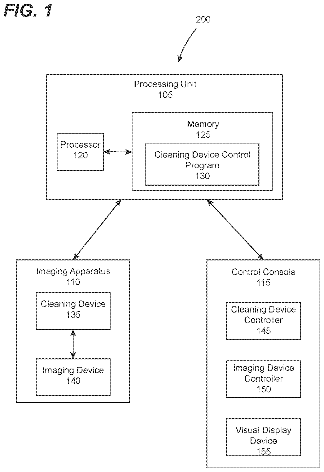
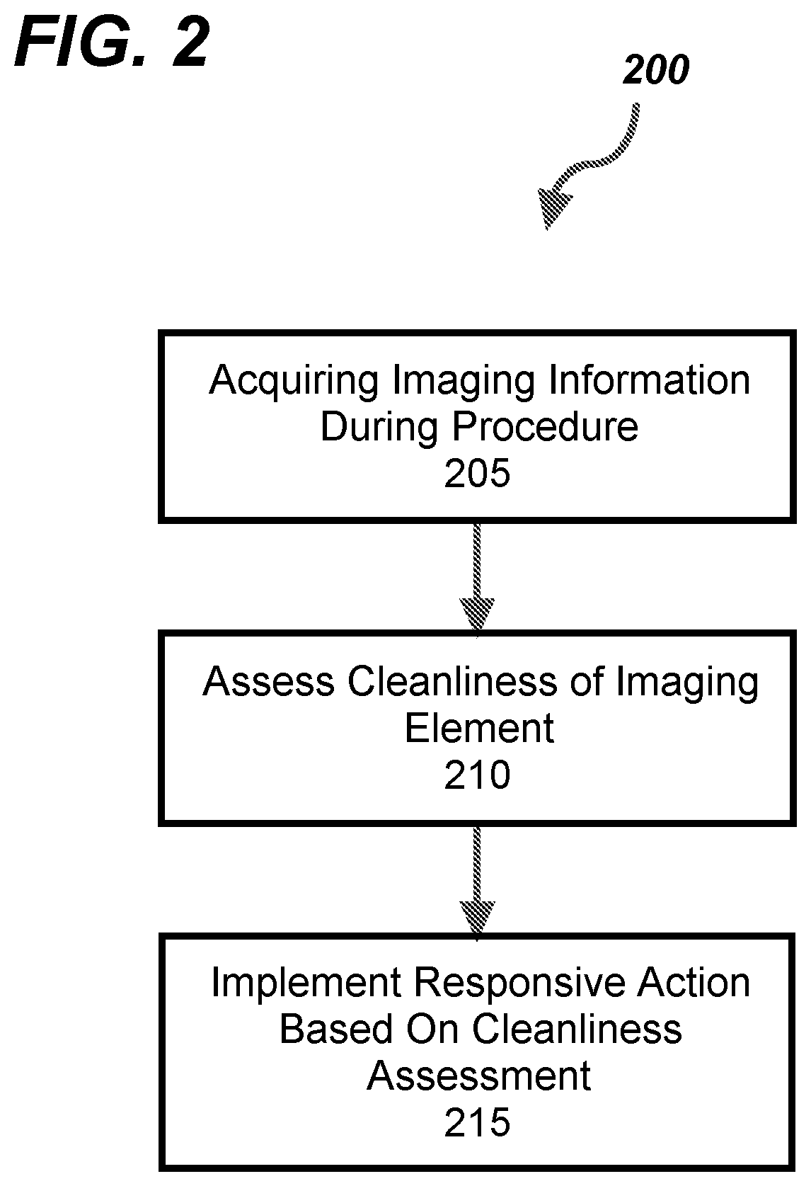
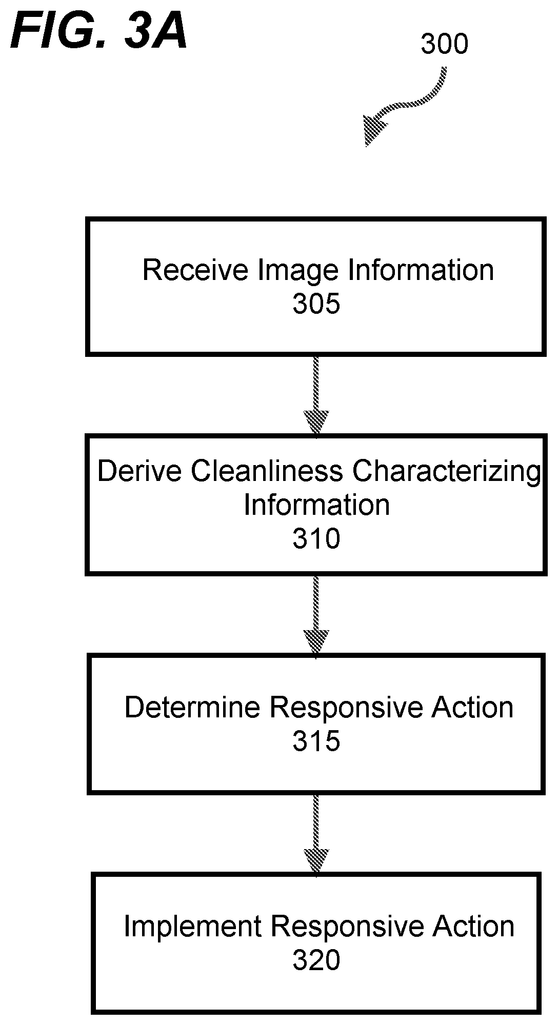
[0042]FIG. 1 shows a computer-assisted system 100 according to one or more embodiment of the disclosures made herein. The computer-assisted system 100 includes a processing unit 105, an imaging apparat...


PUM


Abstract

Disclosed herein are technological solutions that are configured to limit sub-optimal visualization of the surgical field during robotic and manual laparoscopic surgery. Such technological solutions are configured to systematically assess cleanliness of an imaging element of a laparoscope (or other type of similar imaging apparatus) and take action for enabling or causing the imaging element to be cleaned. In preferred embodiments, assessment of the cleanliness of the imaging element provides information that can be used for enabling or causing cleaning of the imaging element to be performed in-vivo in either a manual, semi-autonomous or autonomous manner. In this manner such technological solutions advantageously enable the surgical field during surgery to be more efficiently and consistently maintained in an optimal condition.

Description

FIELD OF THE DISCLOSURE[0001]The disclosures made herein relate generally to imaging devices and implements and, more particularly, to methods, systems and controllers for facilitating cleaning of an imaging element of an imaging device.BACKGROUND[0002]There are many types of operational procedures that require visualization of structures located within an enclosed cavity of a body of material (i.e., a body cavity). Such operational procedures are known to use an imaging device having a portion thereof that is insertable into the body cavity for acquiring imaging information of structures within the body cavity. A prime example such an operational procedure is a surgical procedure that requires imaging within a body cavity of a patient.[0003]It is known that a surgeon's visualization of the surgical field frequently becomes sub-optimal during surgery within a body cavity (e.g., laparoscopic surgery), thereby requiring cleaning of the imaging element of the imaging element. Such sub-...

Claims


Application Information

Patent Timeline
IPC IPC(8): H04N5/217G06T7/00A61B1/313A61B34/37A61B1/12A61B1/00A61B34/00A61B34/30
CPCH04N5/217A61B1/00006A61B1/126A61B1/3132A61B34/25A61B34/37G06T7/0002A61B2034/302G06T2207/30168A61B90/70A61B2090/701G06T7/0014G06T2207/10068G06T2207/20081G06T2207/20084G06T2207/30092A61B1/000094A61B1/000096H04N23/811A61B1/000095H04N23/81
Inventor ALAMBEIGI, FARSHIDCOHEN, ALEXANDERIDELSON, CHRISTOPHER R.RYLANDER, CHRISTOPHER
Owner CLEARCAM INC
Learn More