
Magnetic drop-away arrow rest

a drop-away arrow and magnetic technology, applied in the field of arrow rests, can solve the problems of mechanical parts, particularly springs, that cannot be used in various mechanisms, and cannot be used in white arms/cold weapons, etc., and achieve the effects of reducing the tendency for mechanical wear and tear, and reducing the number of structural moving parts

Active Publication Date: 2017-02-14
GRACE ENG
View PDF9 Cites 2 Cited by
  • Summary
  • Abstract
  • Description
  • Claims
  • Application Information

AI Technical Summary

Benefits of technology

[0017]The arrow rest of the current embodiments provides a consistently functioning, programmable, highly tunable arrow rest. The arrow support arm can be efficiently and consistently moved from a rest position to a support position and vice versa. With the coded magnets, the overall number of structural moving parts can be reduced, as well as the propensity for mechanical wear and tear.

Problems solved by technology

While this provides generally consistent operation, sometimes the mechanical parts, particularly the springs, can fail due to excessive wear and / or friction.
Further, the parts of the various mechanisms can become worn so that tolerances are no longer acceptable and the rests do not consistently fall, or do not consistently return to a loaded state.
While this arrow rest assists in moving the rest, it is rather large and bulky, and the magnets forward and rearward of the support arms of the teeter totter structure can require fine tuning to consistently drop the arrow rest.

Method used


Image

  • Magnetic drop-away arrow rest
  • Magnetic drop-away arrow rest
  • Magnetic drop-away arrow rest

Examples


Embodiment Construction

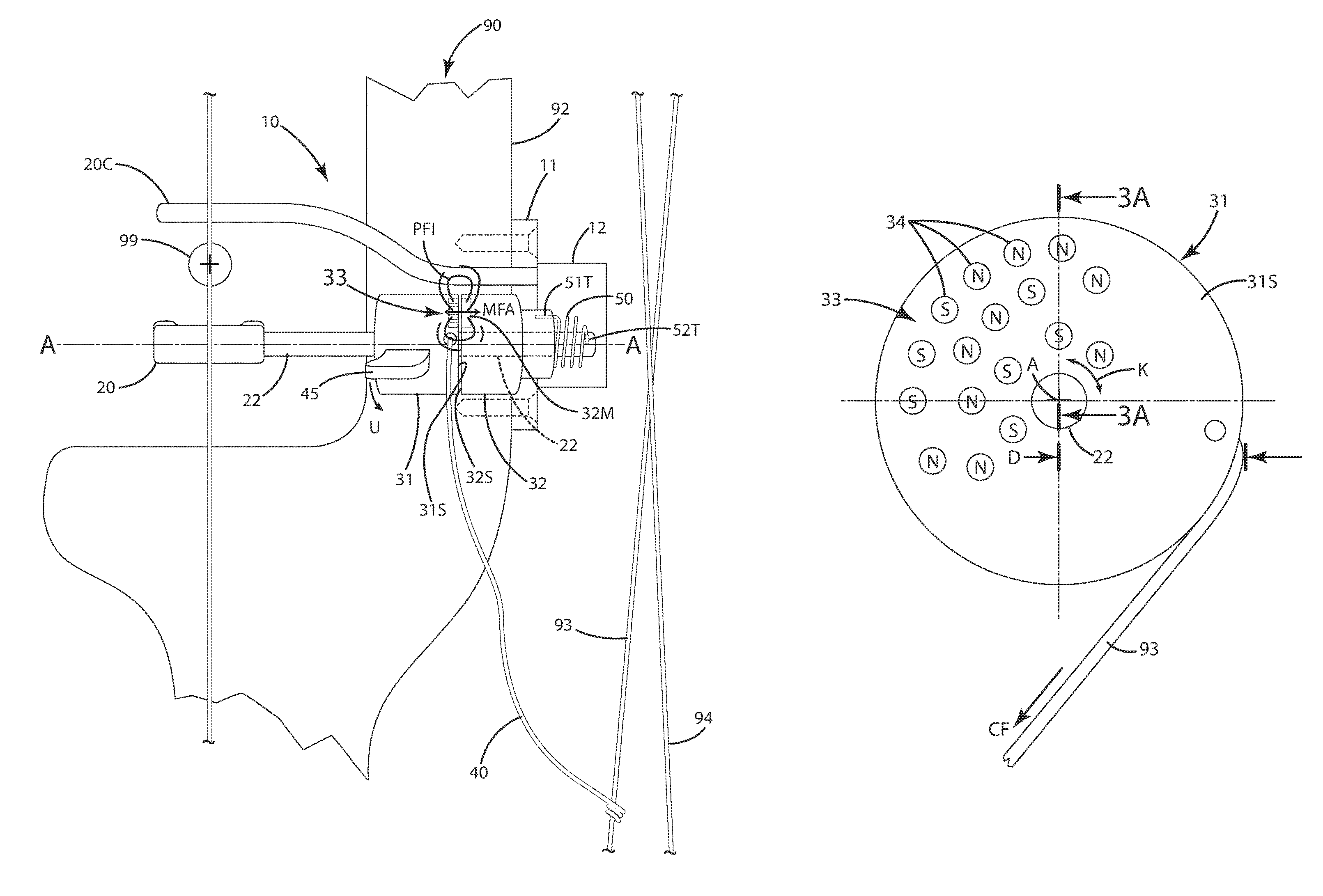
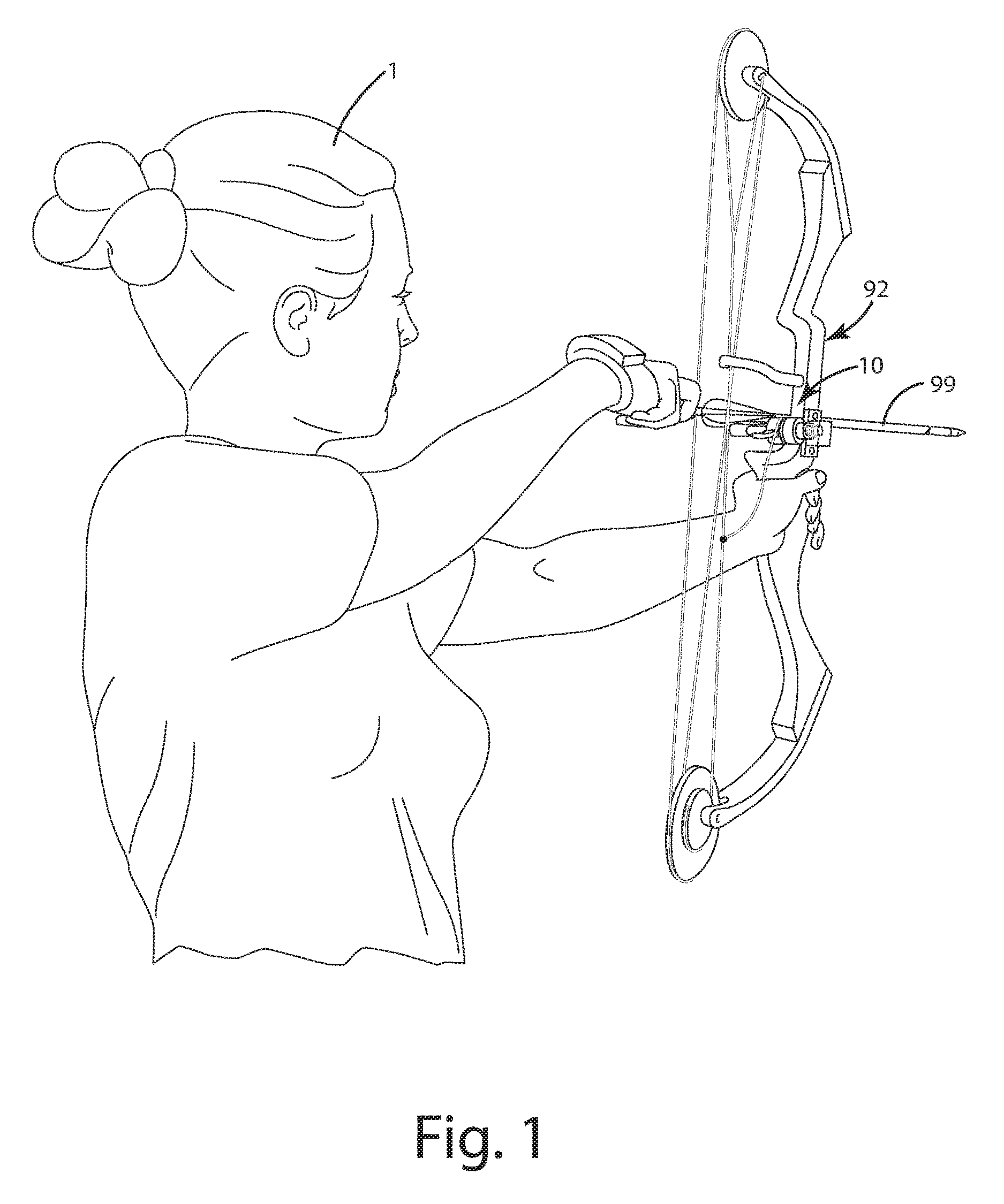
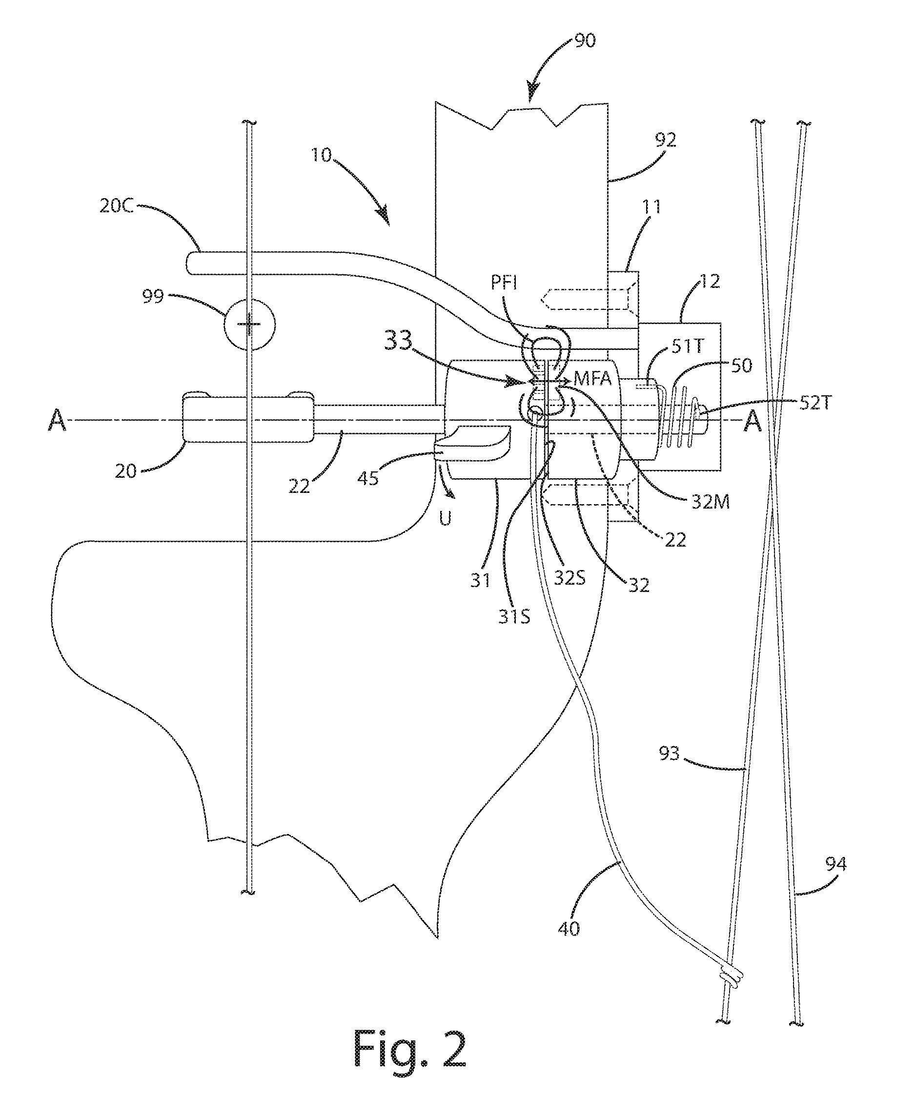
[0036]A drop away arrow rest constructed in accordance with a current embodiment is illustrated in FIGS. 1-5 and generally designated 10. The drop away arrow rest is mounted to a bow 90 and in particular a bow riser 92. The rest can be mounted with a bracket 11 which can include features enabling the arrow rest to be adjusted for windage and / or elevation by manipulating and / or moving fasteners within respective slots (not shown).

[0037]In general, the rest 10 is configured so that its support arm 20 can capture and support an arrow 99. The support arm 20 is actuatable and moveable from the rest position shown in FIG. 2 to the support position shown in FIG. 5 via operation of first and second magnetic elements 31 and 32. The first magnetic element 31 can exert a predetermined force PF1 on the second magnetic element 32, which in this embodiment can be a ferrous material 32M disposed in or on or associated with the second magnetic element. Optionally, the ferrous material 32M can be in...


PUM


Abstract

A drop away arrow rest includes programmable or coded magnets that selectively move an arrow support arm to predetermined positions, such as a support position to hold an arrow, or a rest position to move out of the way of an arrow as it is launched from an archery bow.

Description

BACKGROUND OF THE INVENTION[0001]The present invention relates to arrow rests, and more particularly to magnetically actuated arrow rests and related methods of operation.[0002]Most archery bows are equipped with an arrow rest that holds an arrow before it is shot from the bow. One common arrow rest is referred to as a “drop away” arrow rest. This rest precisely and accurately positions the arrow when the bow (and thus, the bowstring) is at full draw, but drops rapidly away from the arrow upon release of the bowstring. Accordingly, as the arrow is shot from the bow, the rest does not contact the arrow for its full length or the arrow's fletching, which would otherwise divert the arrow from its intended trajectory.[0003]A variety of drop away arrow rests exist. One type of rest is a forward falling rest. This type of rest includes an arrow support that rotates forward and downward, moving from a loaded or cocked position to a relaxed position. Another type of a drop-away arrow rest i...

Claims


Application Information

Patent Timeline
Patent Type & Authority Patents(United States)
IPC IPC(8): F41B5/22F41B5/14
CPCF41B5/143
Inventor GRACE, JR., LOUIS
Owner GRACE ENG
Learn More