
Inhibiting reflux in a heated well of an in situ conversion system

a technology of in situ conversion system and heated well, which is applied in the direction of ohmic-resistance heating, insulation, and wellbore/well accessories, etc., can solve the problems of insufficient injection capacity, difficult to obtain permeability in oil shale formation (e.g., between injection and production wells), and relatively high operating costs

Inactive Publication Date: 2005-12-08
SHELL OIL CO
View PDF99 Cites 115 Cited by
  • Summary
  • Abstract
  • Description
  • Claims
  • Application Information

AI Technical Summary

Benefits of technology

The invention describes a way to produce oil and gas from underground deposits by using heating equipment and pipes that help bring these gases up to the surface. Divers are also used to control where the liquid part of the gas gets directed after it has been formed. This technology can improve how we extract energy from underground resources.

Problems solved by technology

This patent discusses different ways to improve the economic production of hydrocarbons, hydrogen, and other products from various hydrocarbon containing formations. One method involves applying heat to the formation to create new channels and remove existing obstacles to flow within the formation. Another approach includes placing electrodes in the well to generate currents and use them to provide power to the formation. Other techniques involve introducing fluids like water or vapor into the formation to aid in the removal of materials. Despite all this work, certain types of hydrocarbon formations remain challenging when it comes to finding cost-effective methods and increasing injection capacity.

Method used


Image

  • Inhibiting reflux in a heated well of an in situ conversion system
  • Inhibiting reflux in a heated well of an in situ conversion system
  • Inhibiting reflux in a heated well of an in situ conversion system

Examples


Embodiment Construction

[0196] The following description generally relates to systems and methods for treating hydrocarbons in the formations. Such formations may be treated to yield hydrocarbon products, hydrogen, and other products.

[0197]“Hydrocarbons” are generally defined as molecules formed primarily by carbon and hydrogen atoms. Hydrocarbons may also include other elements such as, but not limited to, halogens, metallic elements, nitrogen, oxygen, and / or sulfur. Hydrocarbons may be, but are not limited to, kerogen, bitumen, pyrobitumen, oils, natural mineral waxes, and asphaltites. Hydrocarbons may be located in or adjacent to mineral matrices in the earth. Matrices may include, but are not limited to, sedimentary rock, sands, silicilytes, carbonates, diatomites, and other porous media. “Hydrocarbon fluids” are fluids that include hydrocarbons. Hydrocarbon fluids may include, entrain, or be entrained in non-hydrocarbon fluids such as, hydrogen, nitrogen, carbon monoxide, carbon dioxide, hydrogen sul...


PUM


Abstract

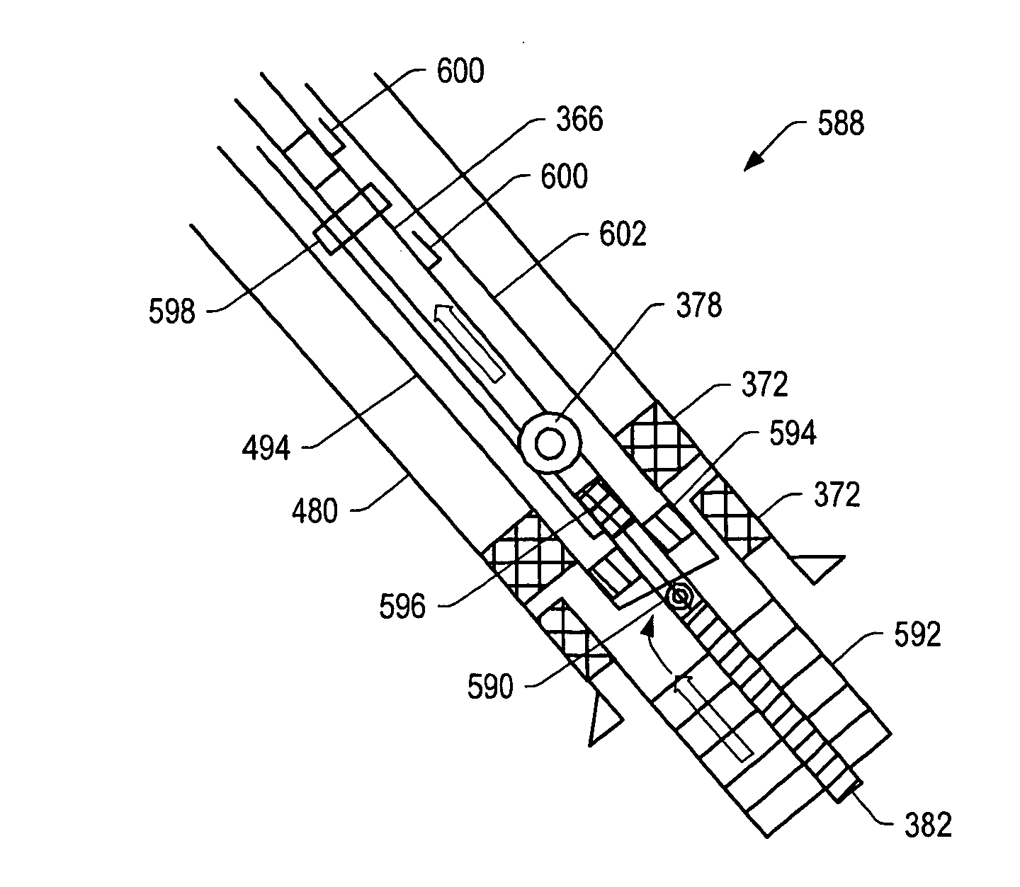
Certain embodiments provide a method for treating a subsurface formation. The method includes using heaters to form a heated portion of the subsurface formation. A production conduit is used to direct formation fluid in a vapor phase from the heated portion of the subsurface formation towards a surface of the subsurface formation. Condensate of the vapor phase formation fluid is formed in or near the production conduit. Condensate of the vapor phase formation fluid is diverted to a desired location.

Description


Claims


Application Information

Patent Timeline
Owner SHELL OIL CO
Learn More