
Display device and driving method thereof

Active Publication Date: 2005-12-08
SAMSUNG DISPLAY CO LTD
View PDF22 Cites 41 Cited by
  • Summary
  • Abstract
  • Description
  • Claims
  • Application Information

AI Technical Summary

Benefits of technology

[0020] The driving transistor may be supplied with a driving signal having first to third voltage levels for the first to the third periods, respectively. The first volta

Problems solved by technology

Although a polysilicon TFT has several advantages, disadvantages of the polysilicon TFT include a complexity of manufacturing polysilicon, which thereby increases manufacturing costs.
In addition, it is difficult to make a large OLED employing polysilicon TFTs.
However, an OLED employing amorphous silicon TFTs exhibits a deterioration of bias stress stability.

Method used


Image

  • Display device and driving method thereof
  • Display device and driving method thereof
  • Display device and driving method thereof

Examples


Embodiment Construction

[0027] The present invention will be described more fully hereinafter with reference to the accompanying drawings, in which preferred embodiments of the invention are shown.

[0028] In the drawings, the thickness of layers and regions are exaggerated for clarity. Like numerals refer to like elements throughout. It will be understood that when an element such as a layer, region or substrate is referred to as being “on” another element, it can be directly on the other element or intervening elements may also be present. In contrast, when an element is referred to as being “directly on” another element, there are no intervening elements present.

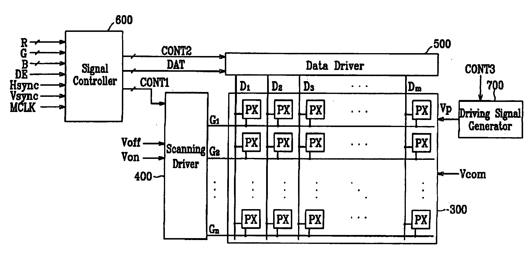
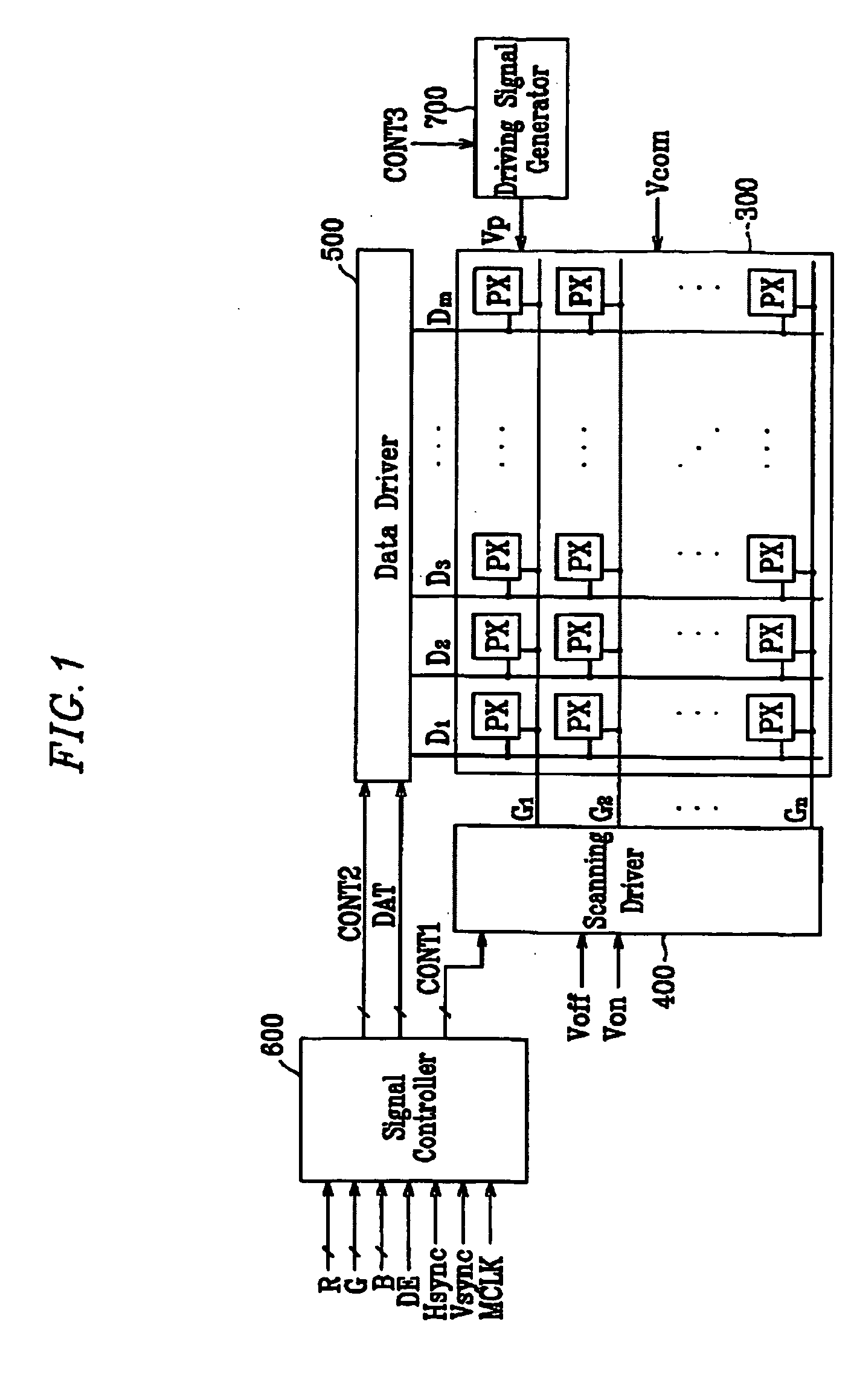
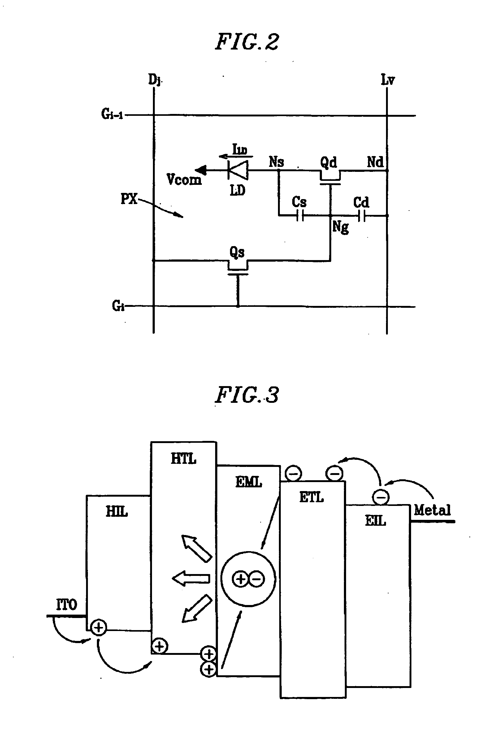
[0029] Referring to FIGS. 1-3, an organic light emitting display (OLED) according to an exemplary embodiment of the present invention will be described in detail.

[0030]FIG. 1 is a block diagram of an OLED according to an exemplary embodiment of the present invention. FIG. 2 is an equivalent circuit diagram of a pixel of an OLED according to an ...


PUM


Abstract

A display device is provided, which includes: light emitting elements; switching transistors transmitting data signals in response to scanning signals; driving transistors, each driving transistor electrically connected to a driving signal line and one of the switching transistors and supplying a current to the light emitting elements in response to an output signal of the one of the switching transistors and the driving signal of the driving signal line; and a first capacitor electrically connected between each driving transistor and each driving signal line; and a second capacitor electrically connected between each light emitting element and each driving transistor, wherein the first and the second capacitors transmit the driving signal by capacitive coupling.

Description

[0001] This application claims priority to Korean Patent Application Nos. 10-2004-0023736, filed on Apr. 7, 2004, the contents of which in its entirety are herein incorporated by reference. BACKGROUND OF THE INVENTION [0002] (a) Field of the Invention [0003] The present invention relates to a display device and a driving method thereof. More particularly, the present invention relates to a light emitting display device and a driving method thereof. [0004] (b) Description of Related Art [0005] Recently there has been a trend toward production of lightweight and thin personal computers and television sets. To support the above-mentioned trend, lightweight and thin display devices are required. Flat panel displays are lightweight and thin in comparison to conventional cathode ray tubes (CRTs) and thus are widely being substituted for CRTs. [0006] Examples of flat panel displays include a liquid crystal display (LCD), field emission display (FED), organic light emitting display (OLED), ...

Claims


Application Information

Patent Timeline
IPC IPC(8): G09G3/30G09G3/32H05B37/02H05B39/04
CPCG09G3/3233G09G2300/0852G09G2330/02G09G2310/0254G09G2320/043G09G2300/0866G09G3/30
Inventor CHOI, JOON-HOOHUH, JONG-MOOJOO, IN-SUKO, CHUN-SEOKCHOI, BEOHM-ROCK
Owner SAMSUNG DISPLAY CO LTD
Learn More