

Method of designing progressive lenses
a technology of progressive addition and lens, applied in the field of progressive addition lenses, can solve the problems of peripheral design together with other design features, may not be available, and may not meet the requirements of wearers, etc., and achieve the effect of maintaining connectivity and being readily assessed
- Summary
- Abstract
- Description
- Claims
- Application Information
AI Technical Summary
Benefits of technology
Problems solved by technology
Method used
Image

Examples
example 1
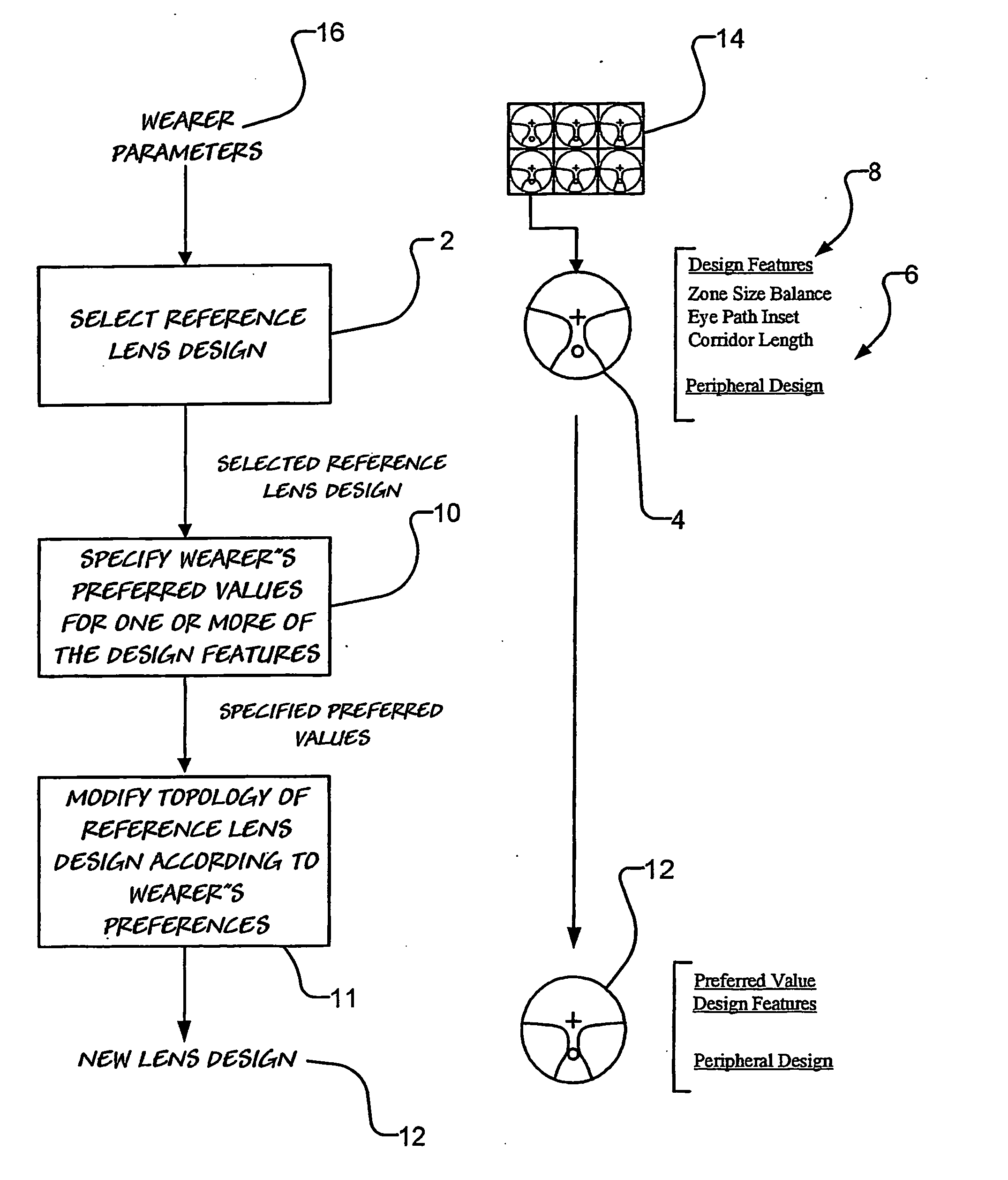
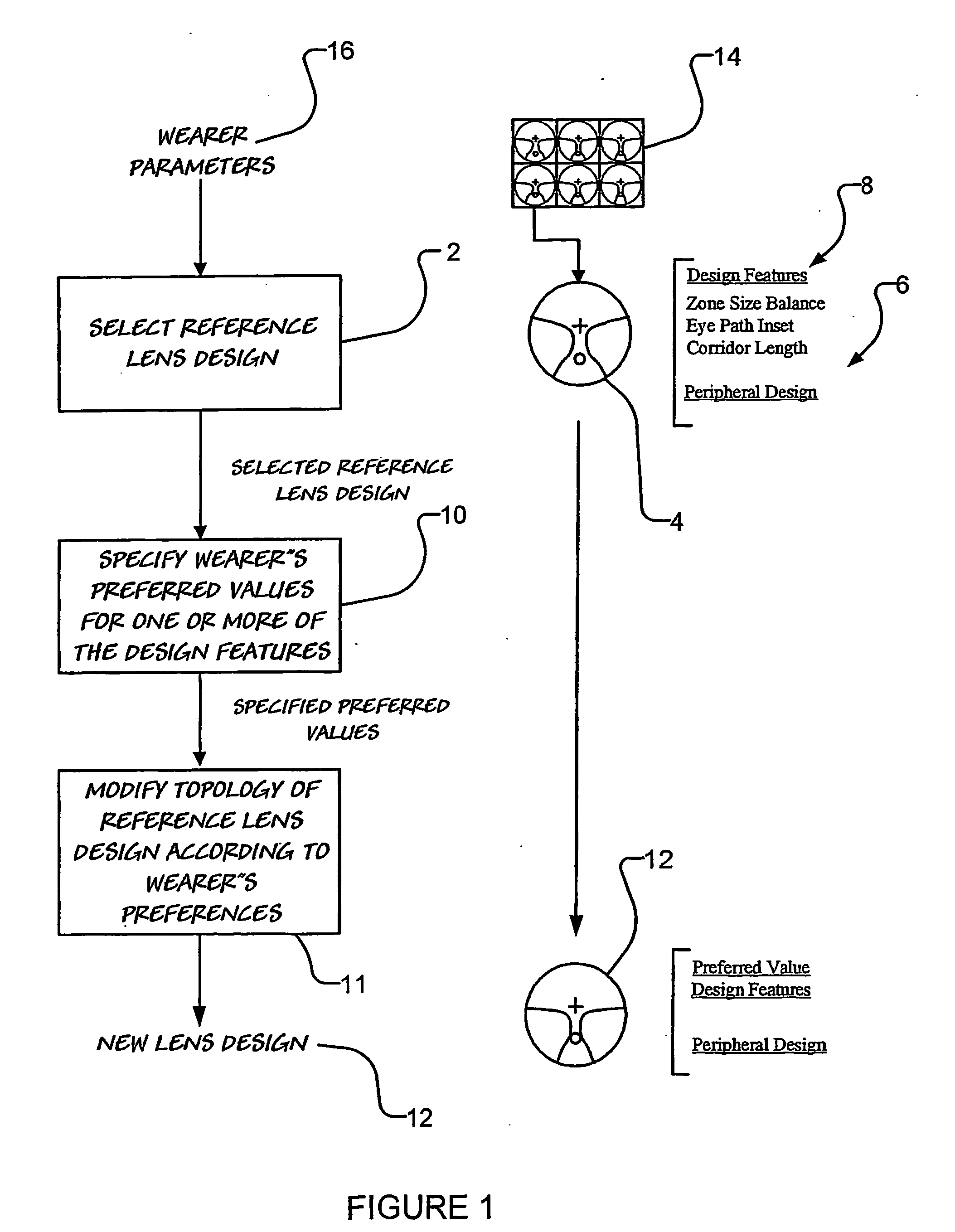
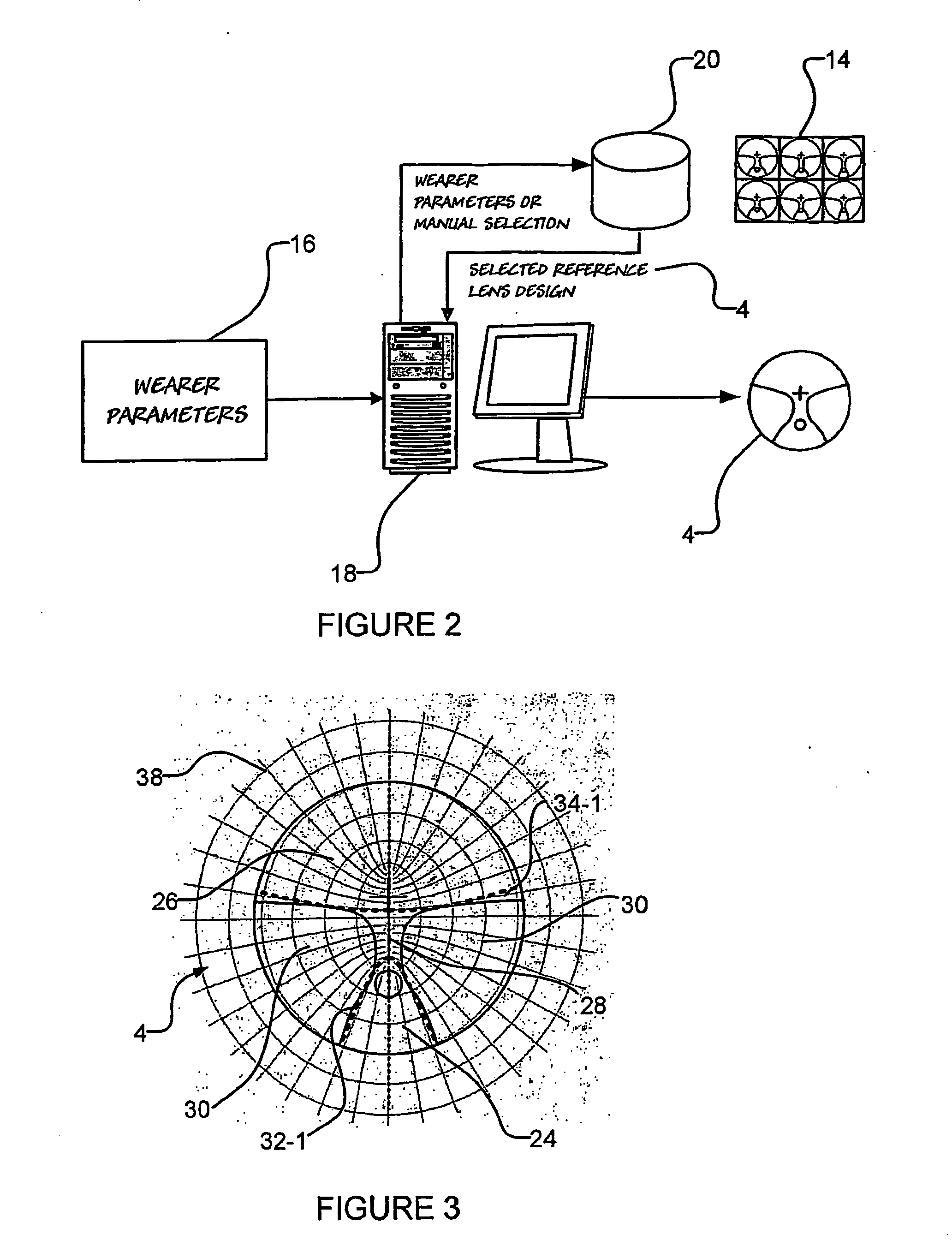
[0120] Turning now to FIG. 4 there is shown a zone balance morphing process 36 for providing a new lens design 12 having a zone size balance which is substantially the same as a wearer's preferred zone size balance. Here, the zone size balance morphing process 36 is accomplished by rotating peripheral regions 30 (refer FIG. 3) on the nasal and temporal sides of the reference lens design 4 in opposite directions.
[0121] The rotation of the peripheral regions 30 (refer FIG. 3) results in one zone (that is the distance zone or the near zone) being enlarged and the other zone being compressed. However, as a result of the zone size balance morphing process 36, the shape of the region of the new lens design 12 which lies in the eye path of the wearer remains substantially the same as the shape of the region of the eye path of the reference lens design 4.
[0122] To accomplish a zone size balance morphing process 36, a suitable zone size balance morphing function ...
example 2
Eye Path Inset Morphing
[0143] Progressive addition lenses may also include an inset.
[0144] Where a selected reference lens design 4 has an inset, then the method of the invention is able to modify the shape of the reference lens 4 design to thereby obtain a new lens 12 design having a zone size balance which corresponds to the wearer's preferred value as well as an inset which is substantially the same as the inset of the reference lens design 4.
[0145] Alternatively, the method may simply provide a new lens design 12 having both a zone size balance and an inset which are substantially identical to the respective wearer's preferred values. That is, the new lens design 12 may have a different inset to the reference lens design 4.
[0146] In this respect, in FIG. 12 there is shown the result of eye path inset morphing process, which may be used together with the zone size balance morphing process 36, to provide a new lens design 12 having both an inset and a zone size balance which a...
example 3
Corridor Length Morphing Process
[0149] In FIG. 13 there is shown the result of a corridor length morphing process, which may be used together with the zone size balance morphing process 36, to provide a new lens design having both a zone size balance and a corridor length which is more closely related to the needs of the wearer.
[0150] As is shown in FIG. 13, the corridor length morphing process applies a morphing function which modifies (that is lengthens or shortens) the corridor length according to the wearer's preferred corridor length value.
[0151] Advantageously, the corridor length morphing process provides a new lens design having substantially the same shape eye path, substantially the same specified angular sizes of the distance zone and near zone, and substantially the same peripheral design as the reference lens.
[0152] As is shown in FIG. 13, a morphing function which is suitable for use in a corridor length morphing process may employ a ‘flared accordion’ expansion 56...
PUM
 Abstract
Description
Claims
Application Information