Mini implant

a mini-implant and implant technology, applied in the field of mini-implants, can solve the problems of loss of tooth function, no longer usable coupling structure between fixture and abutment of permanent implants, socially unaffected in terms of outward appearance, etc., and achieve the effect of maximizing the utility of the mini-implant, facilitating replacement, and very efficient processing

Inactive Publication Date: 2009-07-30
CHOI KYOUNG SOO +1
View PDF6 Cites 12 Cited by
  • Summary
  • Abstract
  • Description
  • Claims
  • Application Information

AI Technical Summary

Benefits of technology

[0015]Embodiments of the present invention are directed to provide a mini implant in which friction is generated at a tapered portion through screw-coupling between a post portion of a fixture and a post hole of an abutment, so that the so-called friction-lock technique can be employed to not only complete the coupling of the fixture and abutment without relying on cement or a mallet, but also uniformly maintain connectivity between the fixture and the abutment, regardless of the dental surgeon.
[0016]Embodiments of the present invention are also directed to provide a mini implant that allows easy replacement of an abutment regardless of the type of fixture, thus enabling selective use of a fixed prosthesis or a removable prosthesis according to requirements.
[0018]Because the present invention employs the friction-lock 5 technique to generate friction at the tapered portion through screw-coupling of the post portion of the fixture and the post hole of the abutment, the coupling structure of the fixture and abutment can be completed without the use of cement or a mallet, and the process can be performed very efficiently.
[0020]Moreover, in the present invention, a screw-coupled abutment can easily be replaced regardless of whether the fixture has been implanted and its type, so that the type of artificial prosthesis to be fixed atop the abutment can be flexibly selected and used from a fixing prosthesis and a removable prosthesis, thereby maximizing the utility of the mini implant.

Problems solved by technology

However, most permanent implants in use today require approximately from 2 to 4 months of healing time for osseointegration, following implantation in the alveolar bone.
Thus, a patient is rendered toothless for the treatment duration, which is undoubtedly a very difficult time for the patient who must endure loss of tooth function, a cosmetic deficit, pronunciation difficulties, and so forth.
When considering the above problems, if a temporary prosthesis were to be implanted during the predetermined period of treatment in which osseointegration on the surface of the permanent implant is completed following implantation of the permanent implant, a patent would not only be able to comfortably chew solid foods and suffer no pronunciation defects, but would also be socially unaffected in terms of outward appearance.
However, the small diameter of a mini implant, as illustrated in FIG. 1, renders the coupling structure between the fixture and abutment of the permanent implant no longer usable.
Conversely, because of its small diameter, a retentive screw cannot be used to couple a fixture to an abutment of a mini implant.
However, because a uni-body mini implant has an integrally formed fixture and abutment, an assortment of different mini implants according to head shape must be prepared, thus requiring procurement of an excessive number of mini implant types.
Thus, while a 2-piece mini implant provided with a separate fixture and abutment is more efficient, because related art 2-piece mini implants must have their fixtures and abutments coupled using cement (adhesive), the time for surgery is not only lengthened, but the coupling method is inconvenient and complicated, and removal of the mini implant is also made difficult.
That is, not only is the degree of preload (that initiates securing of the abutment) inconsistent, but much discomfort is derived from the shock ensuing from the required striking of the abutment with the mallet.
Also, if the mallet cannot be properly used, installing of the abutment is made difficult.
Thus, use of the above micro implant is limited to a large degree.

Method used


Image

  • Mini implant
  • Mini implant
  • Mini implant

Examples


Embodiment Construction

[0032]Features and advantages of the present invention will be more clearly understood by the following detailed description of the present preferred embodiments by reference to the accompanying drawings. It is first noted that terms or words used herein should be construed as meanings or concepts corresponding with the technical spirit of the present invention, based on the principle that the inventor can appropriately define the concepts of the terms to best describe his own invention. Also, it should be understood that detailed descriptions of well-known functions and structures related to the present invention will be omitted so as not to unnecessarily obscure the important point of the present invention.

[0033]Hereinafter, specific embodiments of the present invention will be described in detail with reference to the accompanying drawings.

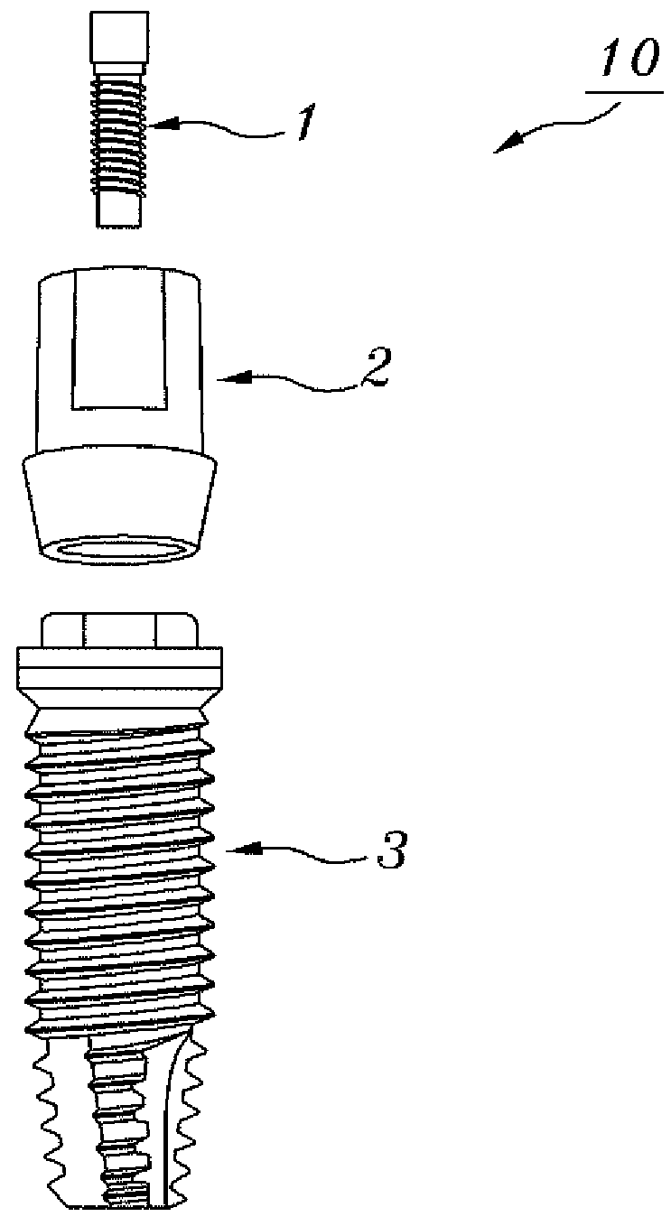
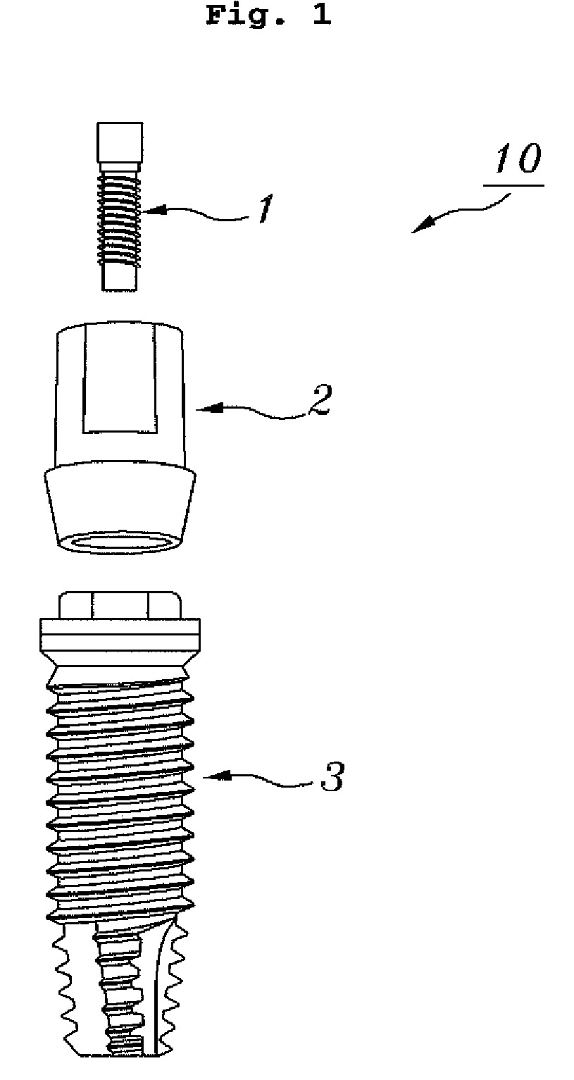
[0034]FIG. 4 is an exploded frontal perspective diagram of a mini implant according to the present invention, and FIG. 5 is a sectional diagra...


PUM


Abstract

Disclosed herein is a mini implant. In the mini implant, friction is generated at a tapered portion through screw-coupling between a fixture's post portion and an abutment's post hole, so that the so-called friction-lock technique can be employed to not only completely couple the fixture and abutment without relying on cement or a mallet, but also uniformly maintain connectivity between the fixture and the abutment, regardless of the dental surgeon. The fixture defines the tapered portion at a top of an implanted portion defining screw threads in an outer periphery thereof. The post portion is formed above the tapered portion and defines screw roots. The abutment defines the post hole in a lower, inner region thereof and a prosthesis mount at an upper region thereof. The post hole defines screw threads corresponding to the screw roots of the post portion.

Description

CROSS-REFERENCES TO RELATED APPLICATION[0001]This patent application claims the benefit of priority under 35 U.S.C. §119 from Korean Patent Application No. 10-2008-0007959 filed Jan. 26, 2008, the contents of which are incorporated herein by reference.BACKGROUND OF THE INVENTION[0002]1. Field of the Invention[0003]The present disclosure relates to a mini implant, and more particularly, to a mini implant in which friction is generated at a tapered portion through screw-coupling between a post portion of a fixture and a post hole of an abutment, so that the so-called friction-lock technique can be employed to not only complete the coupling of the fixture and abutment without relying on cement or a mallet, but also uniformly maintain connectivity between the fixture and the abutment, regardless of the dental surgeon.[0004]2. Description of the Related Art[0005]An implant in general denotes a replacement for restoring lost human tissue, and in the field of dentistry, denotes an artifici...

Claims


Application Information

Patent Timeline
Patent Type & Authority Applications(United States)
IPC IPC(8): A61C8/00
CPCA61C8/0024A61C8/005A61C8/0075A61C8/0074A61C8/006A61C8/00
Inventor CHOI, KYOUNG-SOOYOON, HONG-CHOELJO, YOUNG-SEOUNG
Owner CHOI KYOUNG SOO
Why Eureka
Try Eureka