Rearview mirror element having a circuit mounted to the rear surface of the element

a rearview mirror and circuit technology, applied in the field of rearview mirrors, can solve the problems of increasing the complexity, component count and cost of the mirror assembly, imposing styling constraints, and circuit boards that require many interconnections

Active Publication Date: 2005-12-08
GENTEX CORP
View PDF99 Cites 171 Cited by
  • Summary
  • Abstract
  • Description
  • Claims
  • Application Information

AI Technical Summary

Problems solved by technology

Placement of the circuit board on the rear of the mirror element or within the housing of the mirror assembly can present certain problems.
Specifically, placement of a circuit board within a rearview mirror assembly increases the complexity, component count and cost of the mirror assembly.
In addition, it imposes styling constraints due to the need to make the housing larger and deeper to accommodate and support the circuit board.
Further, circuit boards require many interconnections to the various electronic components within the assembly.
All of these interconnections add to the complexity, cost and component count of the mirror assembly.
Because of the need for all of the above-noted interconnections to other components within the mirror housing, it may not be possible to test the circuit boards and the interconnected components until after final assembly.
This may result in more of the assembly being scrapped in the event of component failure.
Providing circuit components on circuit boards can result in the inadvertent generation of electromagnetic fields at levels that cause interference to other electronic components within the vehicle, such as the vehicle radio.
In addition, circuit components provided on circuit boards may be subject to electromagnetic interference (EMI) from other vehicle accessories thereby resulting in improper operation.

Method used


Image

  • Rearview mirror element having a circuit mounted to the rear surface of the element
  • Rearview mirror element having a circuit mounted to the rear surface of the element
  • Rearview mirror element having a circuit mounted to the rear surface of the element

Examples


Embodiment Construction

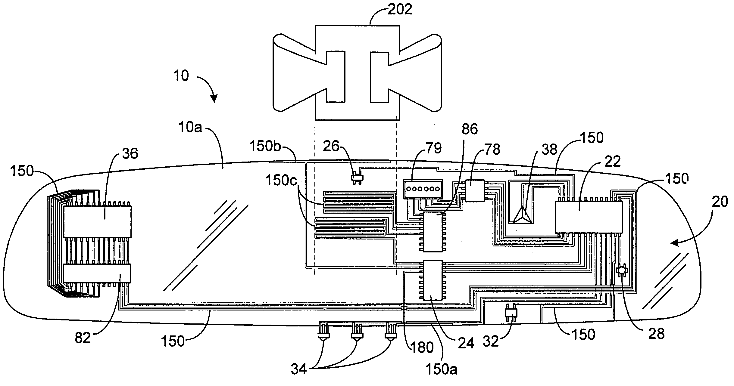
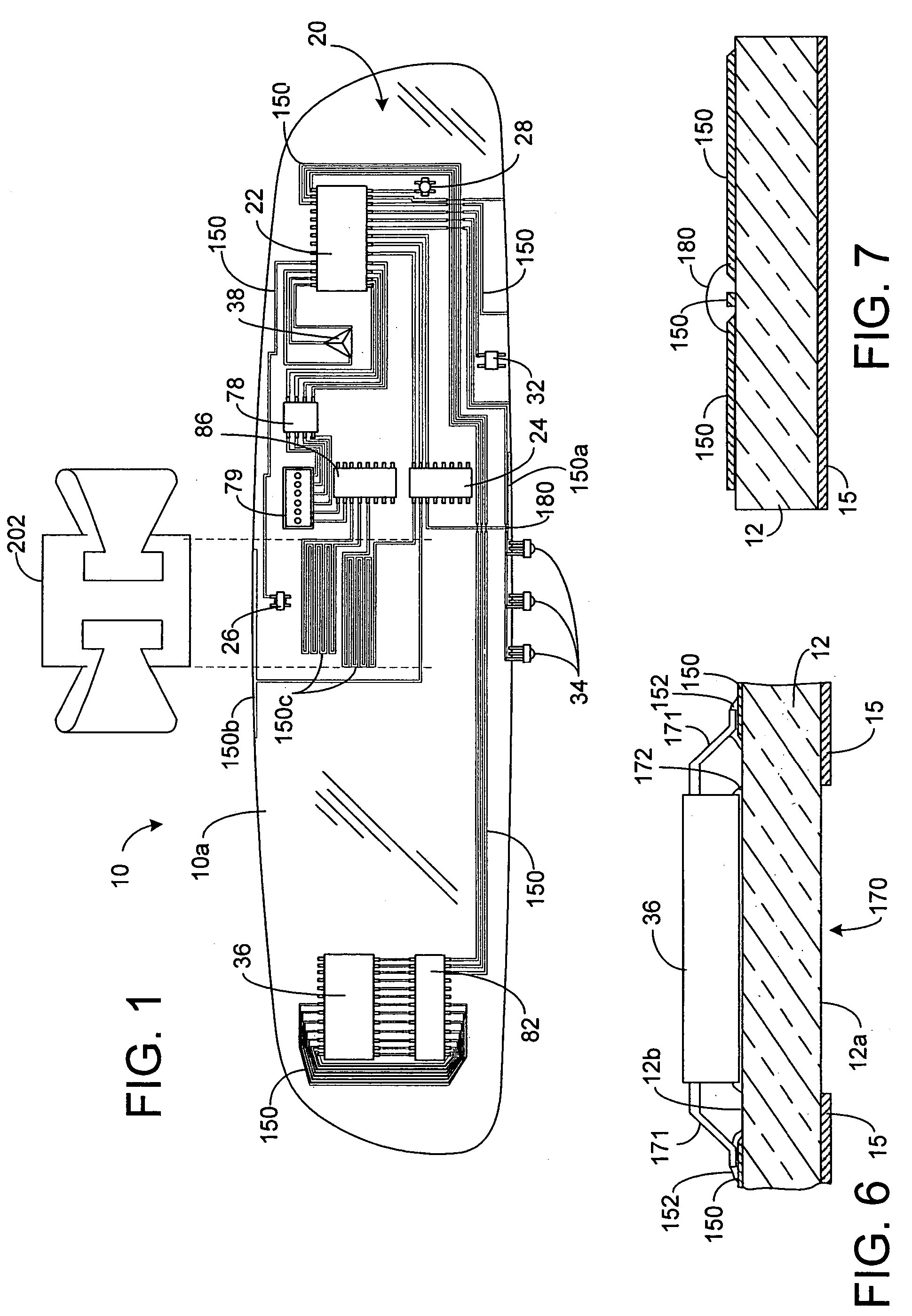
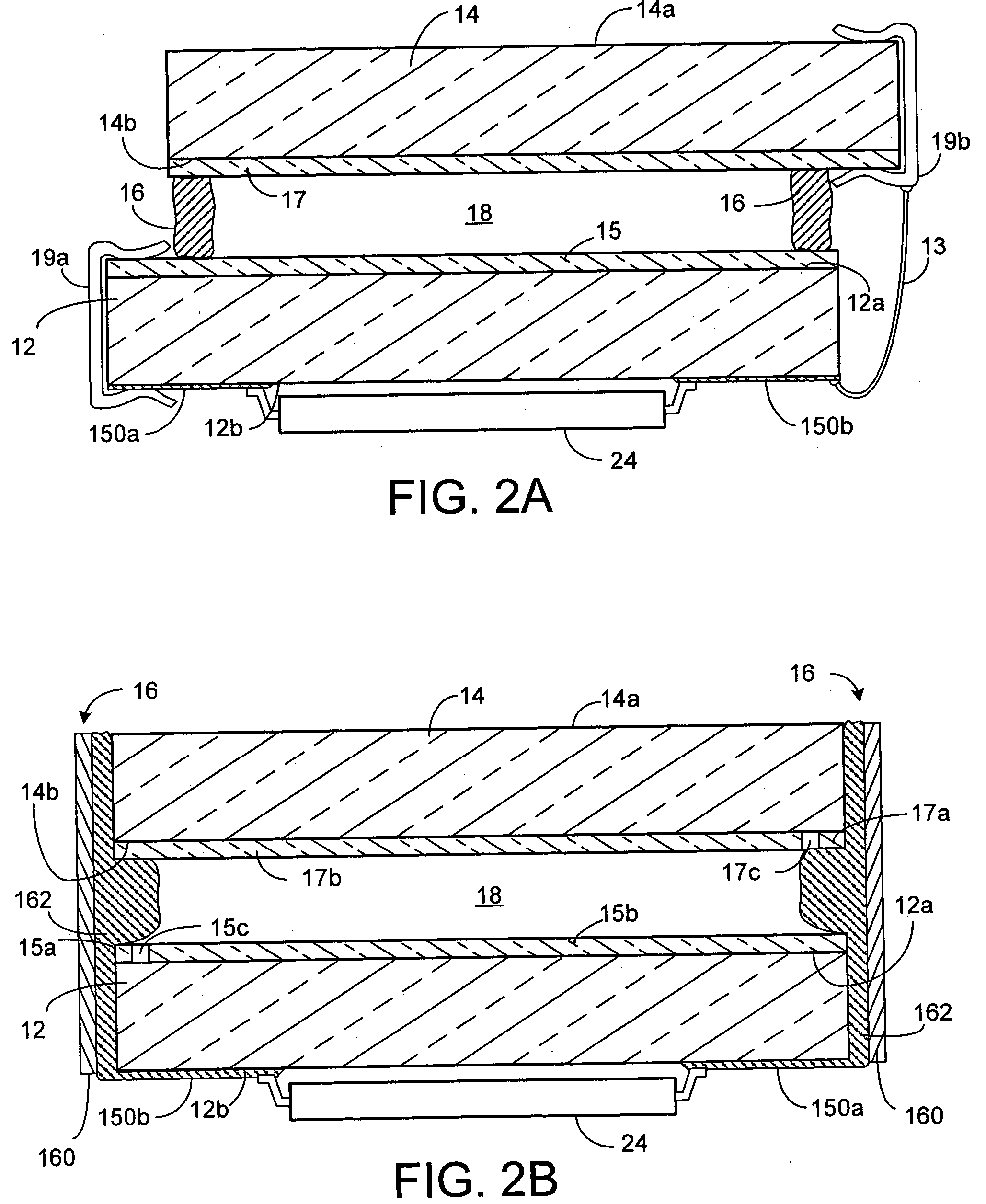
[0034] A vehicle rearview mirror element 10 according to one embodiment of the present invention is shown in FIGS. 1 and 2A. As shown, mirror element 10 comprises: a first substrate 12 having a front surface 12a and a rear surface 12b; a reflective coating 15 disposed on a surface of first substrate 12; and one or more electronic circuit components (20-116) secured to rear surface 12b of first substrate 12.

[0035] Mirror element 10 may be an electrochromic mirror element. As shown in FIG. 2A, an electrochromic mirror element 10a comprises a transparent second substrate 14 positioned in front of first substrate 12. Reflective coating 15 is preferably applied to front surface 12a of first substrate 12. Reflective coating 15 is thus preferably electrically conductive to serve as a first electrode for electrochromic mirror element 10a. Electrochromic mirror element 10a further comprises a transparent conductive layer 17 applied to a rear surface 14b of second substrate 14, which serves ...


PUM

PropertyMeasurementUnit
voltageaaaaaaaaaa
voltageaaaaaaaaaa
transparentaaaaaaaaaa

Abstract

According to the present invention, a rearview mirror comprises a first substrate having a front surface and a rear surface, a reflective coating disposed on a surface of the first substrate, and an electronic circuit component secured to the rear surface of the first substrate. The mirror element may be an electrochromic mirror element comprising a transparent second substrate positioned in front of the first substrate. The electronic component secured to the rear surface may be a component of a drive circuit for the electrochromic mirror element. The rearview mirror element may further comprise electrically conductive tracings provided on the rear surface of the first substrate electrically coupled to the electrical component. The tracings may be used to electrically couple the drive circuit to the electrodes of the electrochromic mirror element. The tracings may be deposited on the rear surface using numerous methods including inkjet printing techniques.

Description

BACKGROUND OF THE INVENTION [0001] This invention relates to rearview mirrors for motor vehicles and, more particularly, to improved electrochromic rearview mirror assemblies and subassemblies. [0002] Existing interior and exterior rearview mirror assemblies may both incorporate one or more electronic accessories that utilize a circuit board to support and interconnect the circuit components of the one or more electronic accessories. Placement of the circuit board on the rear of the mirror element or within the housing of the mirror assembly can present certain problems. Specifically, placement of a circuit board within a rearview mirror assembly increases the complexity, component count and cost of the mirror assembly. In addition, it imposes styling constraints due to the need to make the housing larger and deeper to accommodate and support the circuit board. Further, circuit boards require many interconnections to the various electronic components within the assembly. For example...

Claims


Application Information

Patent Timeline
Patent Type & Authority Applications(United States)
IPC IPC(8): B60R1/08B60R1/12G02B27/00G02F1/15H05K1/02H05K1/03H05K3/32
CPCB60R1/088B60R1/12H05K1/0274H05K1/0306H05K3/321H05K2201/0108H05K2201/10651H05K2201/2036H05K2201/2054H05K2201/10106
Inventor BAUER, FREDERICK T.TURNBULL, ROBERT R.GUARR, THOMAS F.KLOEPPNER, LEROY J.EATON, DAVID L.STRAY, JOEL A.NELSON, BARRY K.
Owner GENTEX CORP
Why Eureka
Try Eureka