
Golf Club Head

a golf club and head technology, applied in the field of golf club head, can solve the problems of less efficient transfer of energy to the golf ball by high surface hardness, significant portion of impact energy loss, and large loss of impact energy in the golf ball, so as to reduce or prevent the shear deformation of the polymer material, and increase the cor

Inactive Publication Date: 2005-12-08
TOPGOLF CALLAWAY BRANDS CORP
View PDF65 Cites 5 Cited by
  • Summary
  • Abstract
  • Description
  • Claims
  • Application Information

AI Technical Summary

Benefits of technology

The present invention provides a solution to prevent the deformation of a polymer layer when a golf ball impacts a golf club head with a polymer coated or layer face. This is achieved by adding a reinforcement structure to the polymer material, which reduces or prevents shear deformation without affecting the normal compliance behavior of the polymer material during impact. This results in a golf club head with greater COR and better durability. The invention can be applied to different types of golf club heads, such as wood-type, iron-type, and putter-type.

Problems solved by technology

While various metals and composites are known for use in the face, several problems arise from the use of traditional face structure and materials.
Thus, during impact of the golf ball with the golf club head, a significant portion of impact energy is lost as a result of the large deformations (0.05 to 0.50 inches) and deformation rates of the high damped golf ball materials, as opposed to the small deformations of the low damped metallic club face (0.025 to 0.050 inches) materials.
A larger portion of this impact energy is lost in the golf ball because the magnitude of the deformation, the deformation rate, and energy loss mechanisms are greater for the golf ball than the face of the golf club head.
The hard insert must be manufactured to a close tolerance to fit within a recess in the face of the golf club, and high surface hardness is less efficient in transferring energy to the golf ball during impact with the golf club.
A homogeneous face structure is simpler to manufacture but is limited to the inherent material properties of the single material comprising the face structure.
However, when a golf ball impacts the face at angles that are not normal to face, such as the case with lofted drivers, shear deformation of the polymer coating introduces energy losses that reduce or eliminate the COR benefit provided by the polymer coating.

Method used


Image

  • Golf Club Head
  • Golf Club Head
  • Golf Club Head

Examples


Embodiment Construction

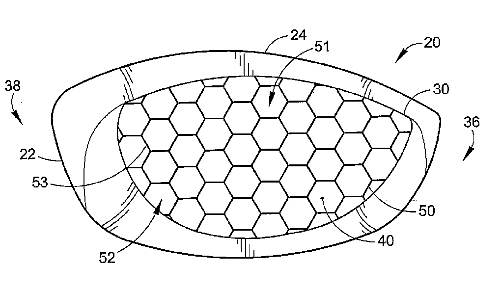
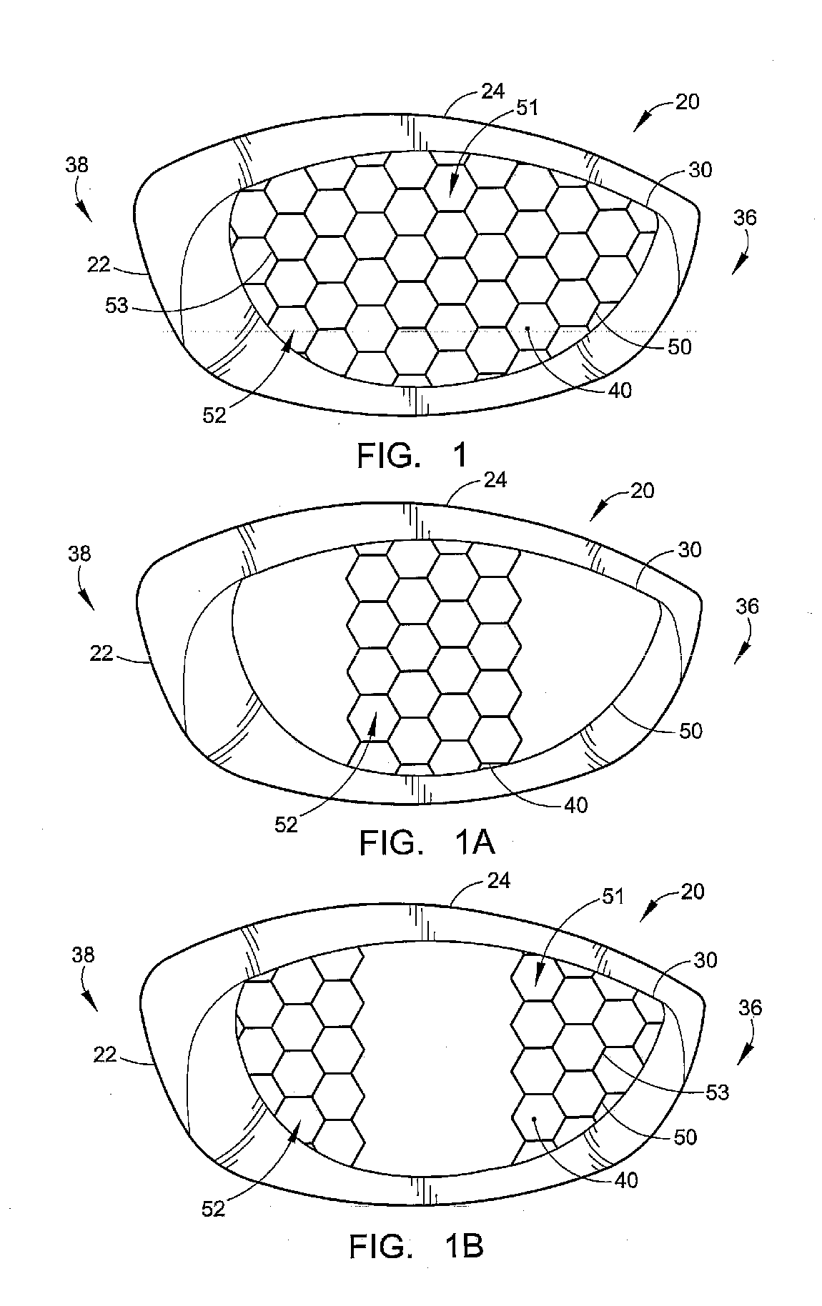
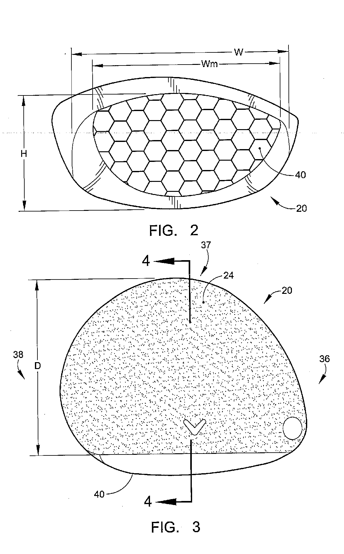
[0049] As shown in FIGS. 1-10, the golf club head of the present invention is generally designated 20. The golf club head 20 of FIGS. 1-10 is a driver, however, the golf club head of the present invention may alternatively be a fairway wood, an iron or a putter. The golf club head 20 has a body 22 that is preferably composed of a metal material such as titanium, titanium alloy, or the like, and is most preferably composed of a cast titanium alloy material. The body 22 is preferably cast from molten metal in a method such as the well-known lost-wax casting method. The metal for casting is preferably titanium or a titanium alloy such as 6-4 titanium alloy, alpha-beta titanium alloy or beta titanium alloy for forging, and 6-4 titanium for casting. Alternatively, the body 22 is composed of 17-4 steel alloy. Additional methods for manufacturing the body 22 include forming the body 22 from a flat sheet of metal, super-plastic forming the body 22 from a flat sheet of metal, machining the b...


PUM

PropertyMeasurementUnit
cell sizeaaaaaaaaaa
thicknessaaaaaaaaaa
depthaaaaaaaaaa

Abstract

A golf club head having a matrix layer composed of an interconnected reinforcement structure and a polymer material is disclosed herein. The matrix layer provides the golf club head with a greater coefficient of restitution during impact with a golf ball. The matrix layer is preferably disposed within a recess in the front wall of the body of the golf club head. The interconnected reinforcement structure is preferably composed of interconnected hexagonal cells.

Description

CROSS REFERENCES TO RELATED APPLICATIONS [0001] This application is a continuation application of U.S. patent application Ser. No. 10 / 249,715, filed on May 2, 2003, which is a continuation-in-part application of U.S. patent application Ser. No. 10 / 063,680, filed on May 7, 2002, now U.S. Pat. No. 6,607,451, which is a continuation application of U.S. patent application Ser. No. 09 / 551,284, filed on Apr. 18, 2000, now U.S. Pat. No. 6,390,932.BACKGROUND OF THE INVENTION [0002] 1. Field of the Invention [0003] The present invention relates to a golf club head. More specifically, the present invention relates to a golf club head with a polymer face. [0004] 2. Description of the Related Art [0005] Technical innovation in the material, construction and performance of golf clubs has resulted in a variety of new products. The advent of metals as a structural material has largely replaced natural wood for wood-type golf club heads, and is but one example of this technical innovation resulting...

Claims


Application Information

Patent Timeline
Patent Type & Authority Applications(United States)
IPC IPC(8): A63B53/04C08G18/10
CPCA63B53/04A63B2053/0416C08G18/10A63B2053/0458A63B2053/0441A63B60/00A63B53/0466A63B53/047A63B2053/0408C08G18/3206A63B53/0441A63B53/0458A63B53/0408A63B53/0416
Inventor EHLERS, STEVEN M.KOSMATKA, JOHN B.NIGRO, ANTHONY V.ERICKSON, MATTHEW J.
Owner TOPGOLF CALLAWAY BRANDS CORP
Learn More