

Distriubte USB KVM switch
- Summary
- Abstract
- Description
- Claims
- Application Information
AI Technical Summary
Benefits of technology
Problems solved by technology
Method used
Image

Examples
Embodiment Construction
[0019] The present invention relates to a system and method for switching and extending KVM interfaces between host interfaces. Provided is a distributed KVM switch where a keyboard and a mouse are emulated to host interfaces of the KVM switch and hosts are emulated to keyboard and mouse interfaces of the KVM switch.
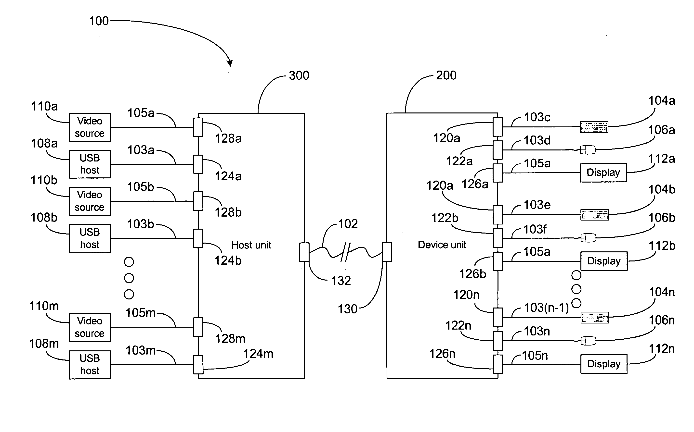
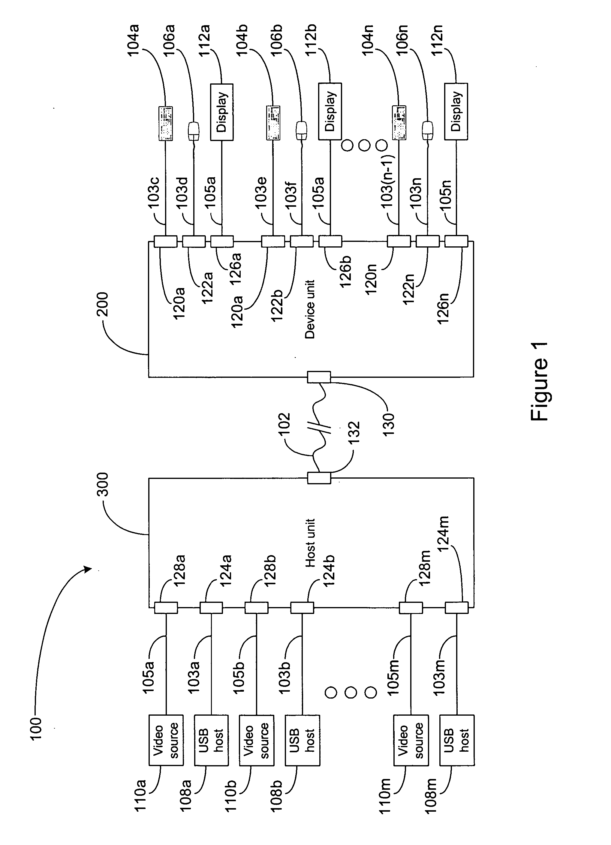
[0020] Turning initially to FIG. 1, a block diagram of a system with a distributed KVM switch is illustrated. The distributed KVM switch 100 is generally positioned between and connectable to at least two USB hosts 108x and at least two sets of USB user input devices, each set including a keyboard 104x and mouse 106x. The distributed KVM switch 100 generally includes a device unit 200, a host unit 300 and a non-USB communications channel 102. The distributed KVM switch 100 may be compatible with USB 1.x, USB 2.x, or both. The hosts 108x may be any USB hosts and are each connectable to the host unit 300 via a USB communications channel 103x. The keyboard 104x and mouse 1...
PUM
 Abstract
Description
Claims
Application Information