
Vehicle, auxiliary baggage carrier

a luggage carrier and auxiliary technology, applied in the field of vehicles and auxiliary luggage carriers, can solve the problems of limited space, frequent inconvenient access, and lack of stowage space, and achieve the effect of increasing the stowage or luggage carrying capacity

Active Publication Date: 2005-12-15
RIGHTLINE GEAR
View PDF13 Cites 1 Cited by
  • Summary
  • Abstract
  • Description
  • Claims
  • Application Information

AI Technical Summary

Benefits of technology

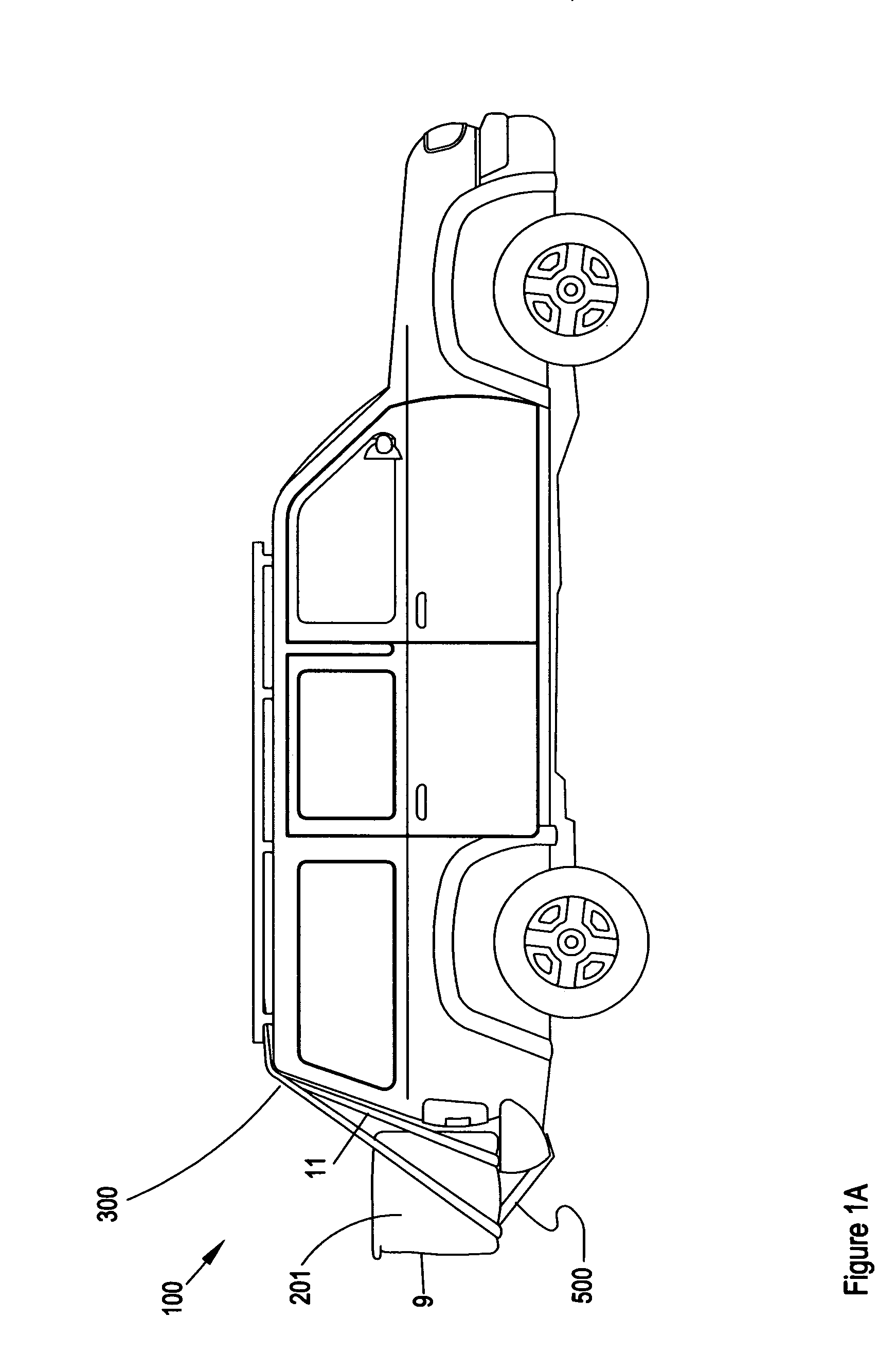
[0013] A primary purpose of the invention is to increase the stowage or luggage carrying capacity of various types of motor vehicles.
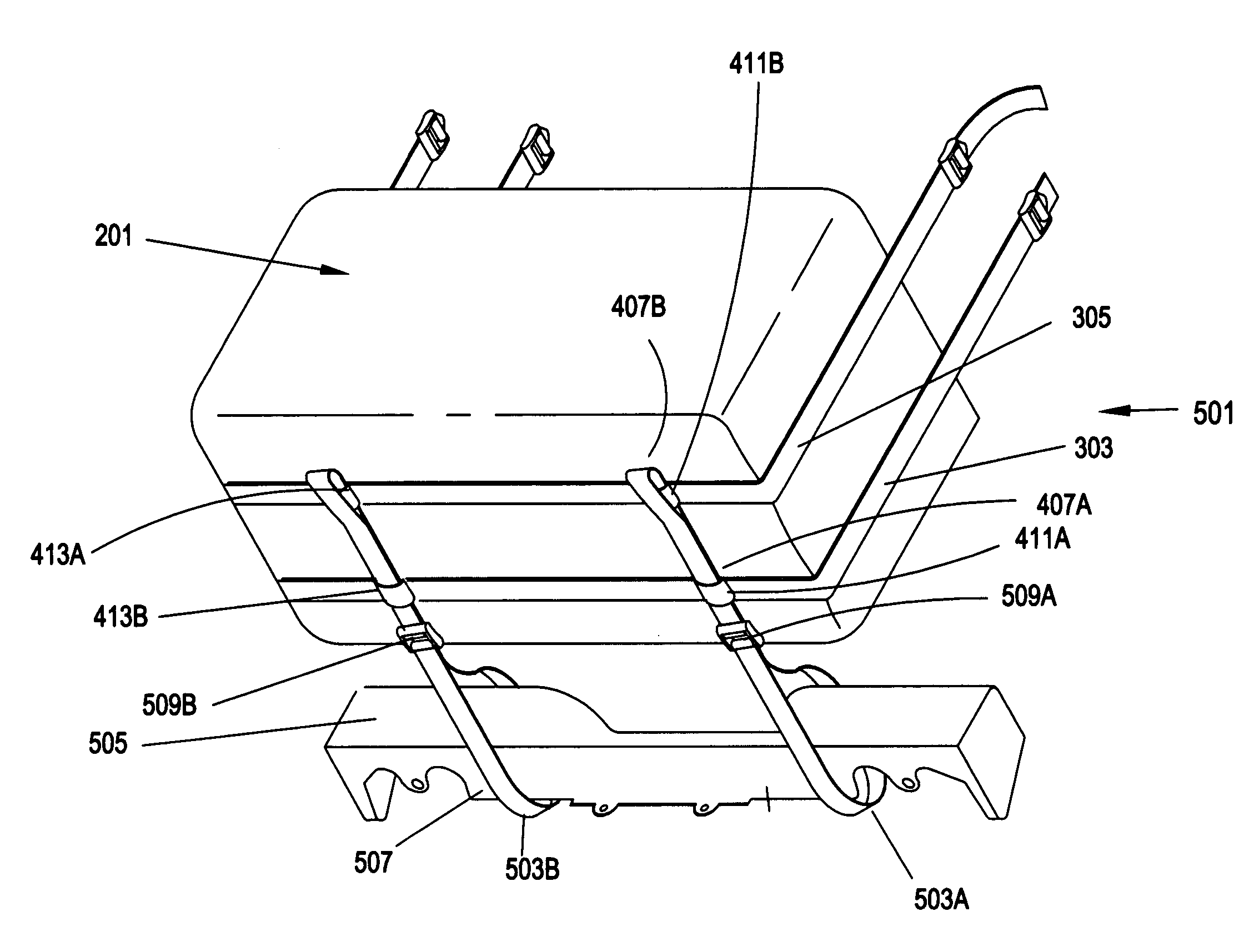
[0015] An additional purpose of the invention is a strap support system that securely attaches a receptacle to the vehicle at both the top and bottom of the vehicle, thereby ensuring stable positioning of the receptacle.

Problems solved by technology

A common consumer criticism of these enormously popular vehicles is the marked lack of stowage space when the vehicle is transporting a full or nearly full load of passengers.
Stowage space, generally regardless of make or model is limited to a small area behind the rear most seat, and depending on seating configuration, this space may be restricted.
The amount of space is limited and frequently inconvenient to access.
All represent a significant source of wind resistance and drag when the vehicle is operated at highway speeds.
All, because of their position on the roof of the vehicle, are exposed to potential damage on the road.
Many are inconvenient to load / unload or access to recover stored items.
Many, because of the roof position, have moderate weight limitations.
U.S. Pat. No. 6,649,655 issued Jul. 22, 1997 to Kerner describes and claims a “luggage rack for a motor vehicle with a steeply inclined end.” The device is in fact a mechanism by which heavy loads can be lifted to a car top carrier fixed to the roof of the vehicle with a body style in which the back is inclined such that lifting and reaching to position the load on the carrier may be difficult.

Method used


Image

  • Vehicle, auxiliary baggage carrier
  • Vehicle, auxiliary baggage carrier
  • Vehicle, auxiliary baggage carrier

Examples


Embodiment Construction

[0032] The invention is described in a variety of configurations with respect to the size and shape of a receptacle and with respect to the pattern of attachment of the primary support straps and tie down straps. Regardless of the specific example, the basic function of the primary support straps is to bear the weight of the receptacle and to secure the receptacle to a vehicle. The basic function of the tie down straps is to secure the receptacle to the vehicle body and thereby to minimize lateral swaying of the receptacle when the vehicle is moving. In the following examples, the tie down straps are secured to the receptacle by passing them through guides formed by the attachment of the primary support straps to the receptacle. Directly attaching the tie down straps is also anticipated by the invention and a fully acceptable alternative for each of the following examples.

[0033] As viewed in FIG. 1A, the invention 100 illustrated in its simplest form comprises a six-sided receptacl...


PUM


Abstract

A device to increase the stowage capacity of vehicles that comprises a fabric, box-like or cylindrical shaped receptacle and primary support straps and tie down straps to mount the receptacle on the rear or side of a vehicle and to minimize sway of the receptacle when the vehicle is in motion.

Description

RELATION TO PRIOR APPLICATIONS [0001] This patent application claims the benefit of and priority of Provisional Patent Application No. 60 / 578,756 filed by Schaefer on Jun. 10, 2004 which Provisional Patent Application is hereby incorporated in its entirety, by reference.FIELD OF THE INVENTION [0002] This invention relates to automobile accessories. More specifically, it relates to auxiliary luggage carriers, and even more specifically, it is directed to an auxiliary luggage carrier comprised of a luggage receptacle or container and an attachment system to secure the receptacle on the rear of most vans, sports utility vehicles, and with modifications on the rear of virtually any automobile, or on the side of a vehicle. BACKGROUND OF THE INVENTION [0003] For many families, the sports utility vehicle (SUV), van or minivan, or traditional station wagon has become the vehicle of choice. In an era of smaller sized sedans, the interior space and passenger comfort and capacity are widely re...

Claims


Application Information

Patent Timeline
IPC IPC(8): B60R9/06A47K1/08
CPCB60R9/06
Inventor SCHAEFER, DAVID R.
Owner RIGHTLINE GEAR
Learn More