Circuit breaker

a circuit breaker and circuit breaker technology, applied in the field of circuit breaker, can solve the problems of lowering the current limit capability, damaging the protective cover, and damaging the secondary side of the circuit breaker and the connection device, so as to prevent damage to the wiring

Active Publication Date: 2005-12-15
FUJI ELECTRIC FA COMPONENTS & SYST CO LTD
View PDF10 Cites 10 Cited by
  • Summary
  • Abstract
  • Description
  • Claims
  • Application Information

AI Technical Summary

Benefits of technology

[0017] As described above, according to the present invention, the protection cover made of the insulating material covers the movable contact and is difficult to detach without other components causing an adverse effect such as spreading an arc, thereby preventing damage on a wiring on a secondary side of the circuit breaker and a connection device.

Problems solved by technology

Depending on the material and strength of the protection cover and the pin, the protection cover may break when the pin is clamped with an excessive stress.
When the protection cover is loosely fixed and the protection cover is detached as the moving contact repeats opening and closing, the contact arc can not be extinguished upon an over-current, thereby damaging a wiring on a secondary side of the circuit breaker and a connection device.
Also, the arc may be spread through a metal member such as a pin and the like, thereby lowering current limiting capability.
When the protection cover is damaged, the protection cover may fall off and obstruct a function of the circuit breaker, thereby damaging a wiring on a secondary side of the circuit breaker.

Method used


Image

  • Circuit breaker
  • Circuit breaker
  • Circuit breaker

Examples


Embodiment Construction

[0023] Hereinafter, embodiments of the present invention will be described with reference to the accompanying drawings.

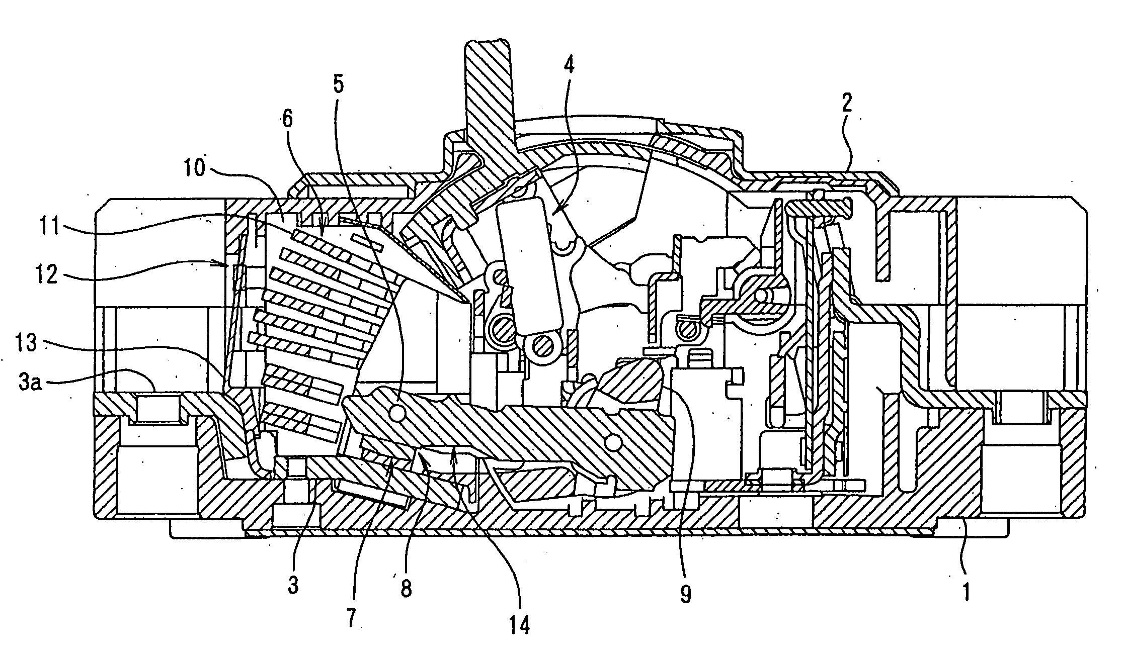
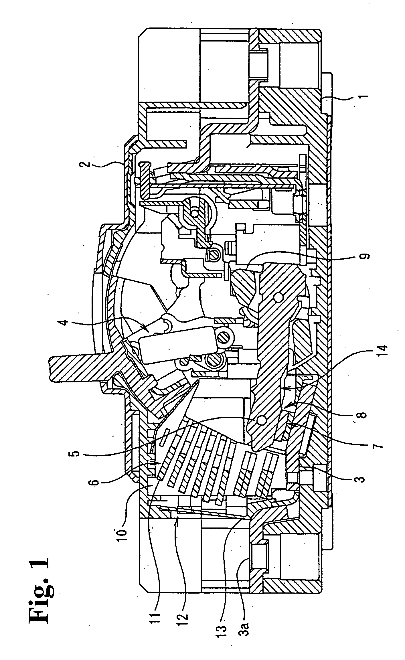
[0024]FIG. 1 is a longitudinal sectional view showing essential parts at a central pole section of a three-pole circuit breaker according to an embodiment of the present invention. In the circuit breaker shown in FIG. 1, a breaking unit is disposed in an insulating container formed of a case 1 and a cover 2, and includes a fixed contact 3 fixed to the case 1 and an elongate plate-shaped movable contact 5 driven to open and close by an opening / closing mechanism 4. An arc extinguish chamber 6 is installed in the breaking unit.

[0025]FIG. 1 shows the breaking unit at the central pole section, and the insulating container is divided into three-phase spaces by phase partitions and a breaking unit corresponding to each phase is housed in each space. The fixed contact 3 has a power-side terminal 3a integrally formed at one end and a fixed contact 7 at the other end.

[0026...


PUM


Abstract

A circuit breaker includes an elongated movable contact having a contact at one end thereof for flowing a current therethrough and the other end rotatably supported with a holder, and a protection cover made of an insulating material for covering and protecting a movable contact from short circuit and discharge. The protection cover is made of only the insulating material, covers the movable contact, and has elasticity to tightly hold the movable contact.

Description

BACKGROUND OF THE INVENTION AND RELATED ART STATEMENT [0001] The present invention relate to a circuit breaker such as a molded case circuit breaker or an earth leakage breaker having a movable contact opened by an electromagnetic repulsive force when a large current such as a short-circuit current flows. In particular, the present invention relates to a circuit breaker having a protection cover made of an insulating material that covers a movable contact to extinguish a contact arc generated when the contact opens. [0002] A protection cover made of an insulating material for a movable contact in a conventional circuit breaker is disclosed in Patent Reference 1 or 2. According to Patent References 1 and 2, the insulating material is disposed near a contact of the movable contact to improve breaking capability. The insulating material having a shape to cover a periphery of the contact is fixed by clamping with a pin penetrating the contact and the insulating material. [0003] Patent R...

Claims


Application Information

Patent Timeline
Patent Type & Authority Applications(United States)
IPC IPC(8): H01H9/30H01H73/18H01H73/02
CPCH01H9/30H01H73/18H01H2203/04H01H2239/032H01H2223/044
Inventor YAMAZAKI, TOMOOMITSUSHIGE, MITSUHIROASAKAWA, KOJIYAMAGATA, HIDETOSATO, AKIFUMI
Owner FUJI ELECTRIC FA COMPONENTS & SYST CO LTD
Why Eureka
Try Eureka