Bandwidth optimization in transport of Ethernet frames

a technology of ethernet frames and bandwidth optimization, applied in the field of telecommunication, can solve the problems of different delays in connection, loss of frames, degradation of service quality, etc., and achieve the effect of avoiding overflow of queues and restoring the maximum bandwidth availabl

Inactive Publication Date: 2005-12-15
ALCATEL LUCENT SAS
View PDF8 Cites 24 Cited by
  • Summary
  • Abstract
  • Description
  • Claims
  • Application Information

AI Technical Summary

Benefits of technology

[0006] In view of the drawbacks and deficiencies of the known and standardized solutions, as described above, the main object of the present invention is to provide a method for avoiding overflow of the receiving queues storing frames carried over different connections having different values of delays; this is achieved by the steps of measuring of the delays of at least two forward connections from a first network element to a second network element following different routes, collecting the values of the delays, comparing the values respect to a defined range of valid values and carrying second frames including header fields and payload fields with encapsulated first frames over the forward connections having the values of the delays within the range and the second frames including only header fields over the forward connections having the values of the delays out of the range, the header fields carrying information for performing the measuring of the delays of the forward connections. The basic idea is to measure the delays of the connections, to collect the values of the measured delays, to define a range of valid values of delays and to transmit the frames over the connections having the delays within the defined range. This solution allows to avoid overflow of the queues because it prevents the filling above the danger value.
[0007] A correlated advantage is the automatic restoring of the maximum bandwidth available from the connections; this is achieved by carrying the frames over those connections where actual delays previously out of the range are within the range. A further object is to define a range of valid values of delays according to delay optimization or bandwidth optimization; this is achieved by assigning to the lower bound of the range the smallest value of the measured delays of the connections and to the upper bound of the range as a predefined maximum value or by assigning to the upper bound of the range the sum of the lower bound and a predefined value, wherein the lower bound is calculated from the measured delays in order to have the maximum number of connections having the values of the delays within the range.

Problems solved by technology

Since each connection follows a different route, the connections can have different delays.
In both cases loss of frames occurs.
According to this solution, data is not lost but there is a degradation of the quality of the service because bandwidth is drammatically reduced in case the transmission is stopped for many connections having big delays.

Method used


Image

  • Bandwidth optimization in transport of Ethernet frames
  • Bandwidth optimization in transport of Ethernet frames
  • Bandwidth optimization in transport of Ethernet frames

Examples


Embodiment Construction

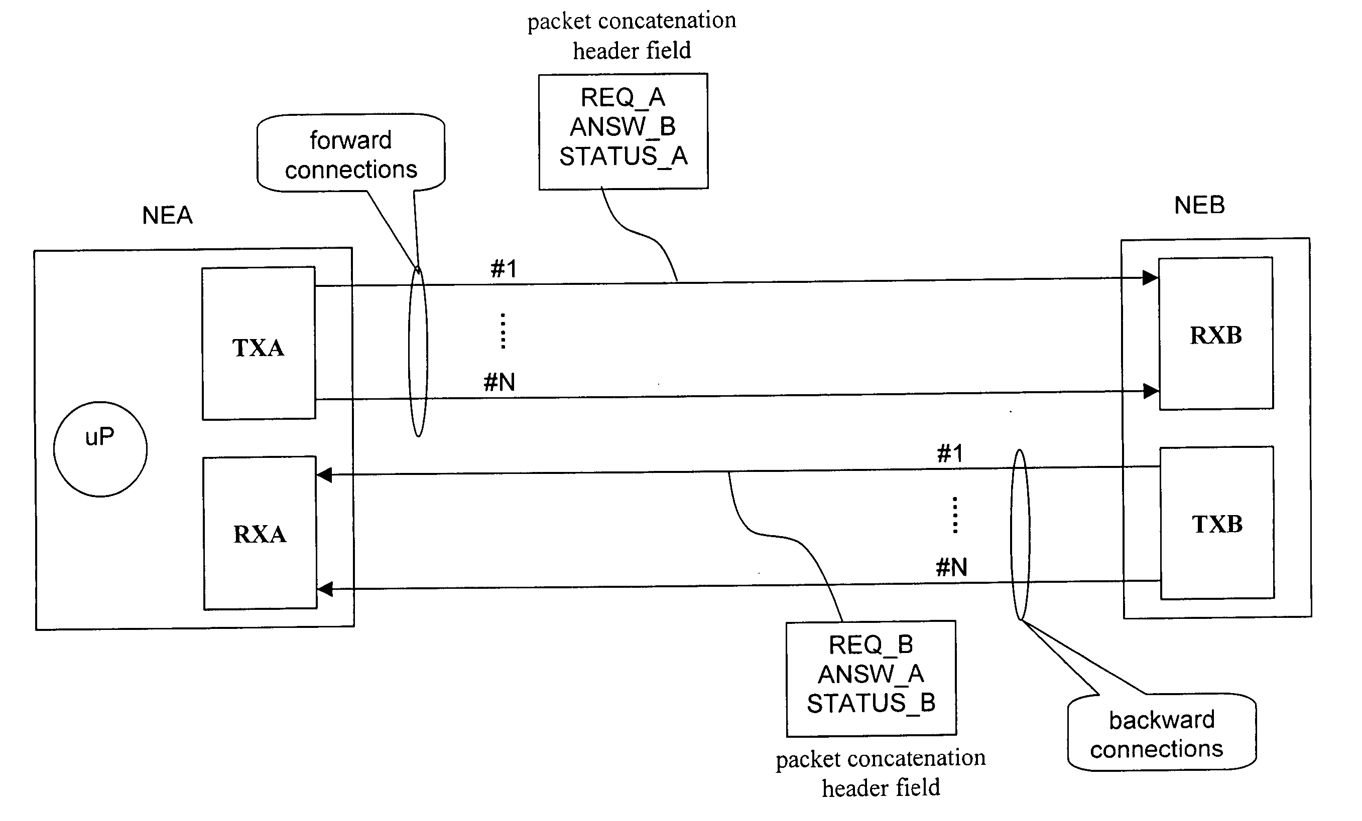
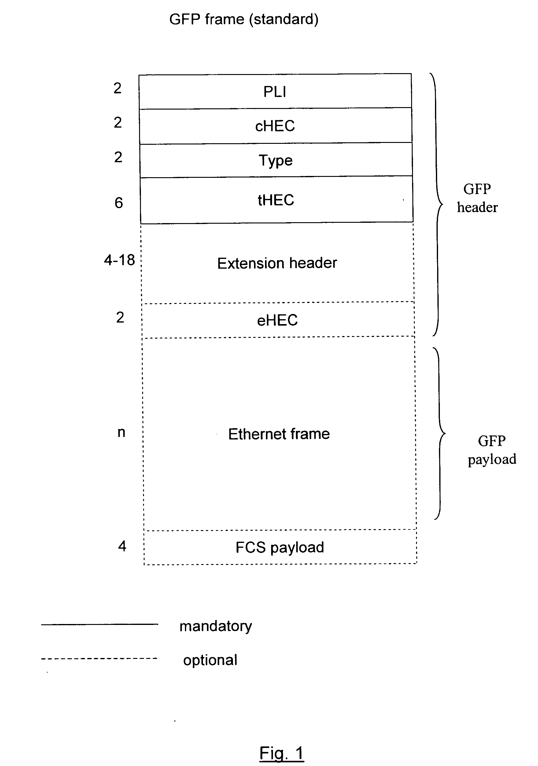
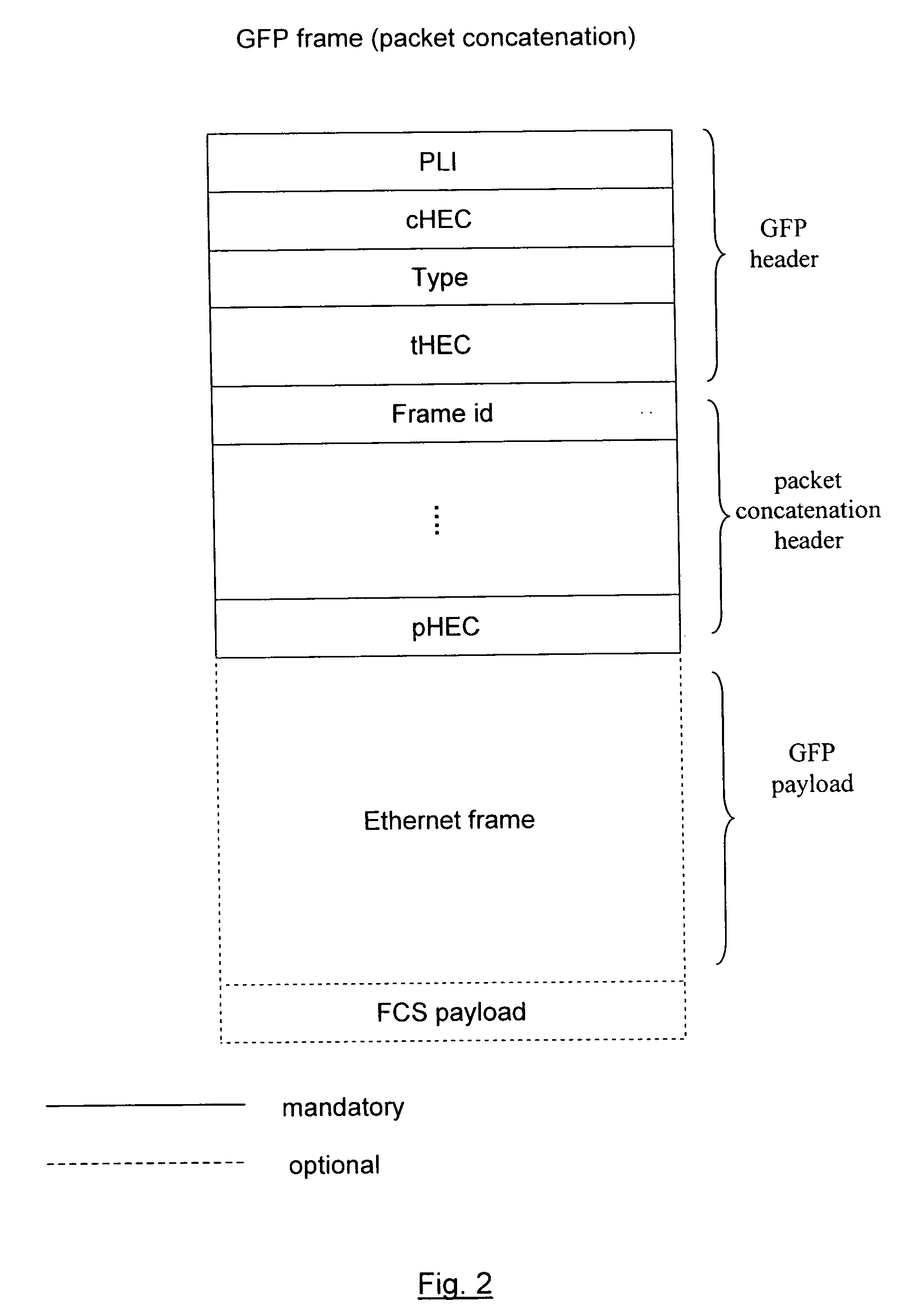
[0013]FIG. 3 shows a first preferred embodiment including two network elements, NEA and NEB, performing the inventive method; each network element includes a transmitter (TXA and TXB) for transmitting the frames and a receiver (RXA, RXB) for receiving the frames and NEA also includes a microprocessor. NEA and NEB are two end network elements, i.e. network elements at the end of the connections, but intermediate network elements can be placed between NEA and NEB: in this case a connection is divided into connection segments, each segment connecting two network elements. At least two forward connections, following different routes, are provided from NEA to NEB and usually the same number of connections from NEB to NEA (bidirectional connections). Ethernet frames are transmitted over the connections from NEA to NEB and viceversa, according to encapsulation into GFP frames and mapping into VCs of an SDH network according to packet concatenation. A GFP frame includes the header field inc...


PUM


Abstract

A method is described for optimizing the transport of Ethernet frames in a telecommunication network over different connections having different delays, in order to avoid overflow of the receiving queues. The method includes measuring of the delays of the connections, collecting the values of the delays, defining a range of valid values, comparing the values of the delays to the defined range and carrying the Ethernet frames over the connections having the values of the delays within the defined range.

Description

FIELD OF THE INVENTION [0001] The present invention relates to the telecommunication field and more in particular to the transport of Ethernet frames over a SDH / SONET / OTN network. Still more in particular, the invention concerns to a method for optimizing the transport of Ethernet frames carried between two network elements over several connections having different delays. [0002] This application is based on, and claims the benefit of, European Patent Application No. 04291464.8 filed on Jun. 10, 2004, which is incorporated by reference herein. BACKGROUND OF THE INVENTION [0003] Ethernet frames are carried in a telecommunication network according to encapsulation into GFP (Generic Frame Procedure ) frames, as defined by International Telecommunication Union (ITU) in ITU-T G.7041 / Y.1303 (December 2001). Referring to FIG. 1, a GFP frame includes a payload field for carrying the Ethernet frame (without the Preamble and the Start of Frame Delimiter) and an header field. Some fields are m...

Claims


Application Information

Patent Timeline
Patent Type & Authority Applications(United States)
IPC IPC(8): H04J3/06H04J3/16H04L1/00H04L12/413H04L12/46H04L12/56
CPCH04J3/0682H04L12/4633H04J3/1617
Inventor MAGGI, DONATOPOZZOLI, ELENARICCIARDI, CARMELATAINA, PAOLO
Owner ALCATEL LUCENT SAS
Why Eureka
Try Eureka