Radiation image sensing apparatus and its driving method

a sensing apparatus and imaging technology, applied in the direction of radioation control devices, instruments, television systems, etc., can solve the problems of poor image quality of sensed images, increased overall apparatus cost, and poor layout of aec control sensors

Inactive Publication Date: 2005-12-22
CANON KK
View PDF15 Cites 13 Cited by
  • Summary
  • Abstract
  • Description
  • Claims
  • Application Information

AI Technical Summary

Benefits of technology

[0021] The present invention has been made in consideration of the aforementioned problems, and has as its object to provide a radiation image sensing apparatus and its driving method, which can adjust (AEC control) the amount of incoming light or dose without requiring high-speed driving.

Problems solved by technology

However, when the AEC control sensors are independently provided to the radiation image sensing apparatus having the 2D sensor matrix so as to adjust (AEC control) the amount of incoming light or dose, the layout of the AEC control sensors poses a problem.
However, in a sensor with 2,000×2,000 pixels or more, a high-speed driving circuit is required, resulting in an increase in cost of the overall apparatus.
Since high-speed driving is required, it becomes difficult for the sensor of the radiation image sensing apparatus to assure a sufficiently long charge accumulation time, charge transfer time, and capacitor reset time, and the like, resulting in poor image quality of a sensed image.

Method used


Image

  • Radiation image sensing apparatus and its driving method
  • Radiation image sensing apparatus and its driving method
  • Radiation image sensing apparatus and its driving method

Examples


first embodiment

[0057] The first embodiment of the present invention will be described below with reference to FIG. 1.

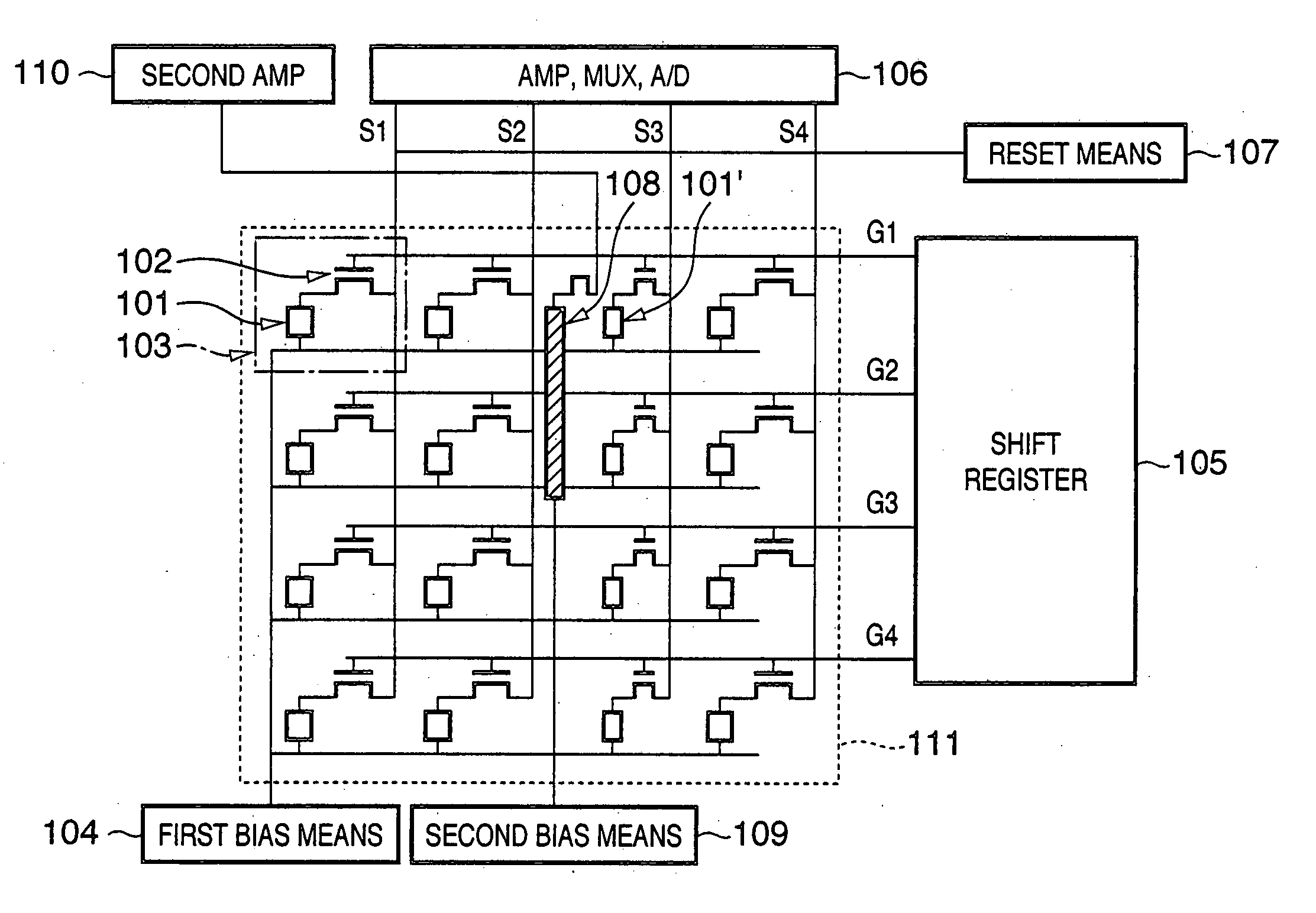
[0058]FIG. 1 is a circuit diagram of a radiation image sensing apparatus of this embodiment. As shown in FIG. 1, the radiation image sensing apparatus of this embodiment comprises a 2D matrix of a total of 16 pixels 103, i.e., 4 cells in the vertical direction×4 cells in the horizontal direction. Each pixel 103 comprises a first photoelectric conversion element 101, and a transistor 102, which is connected to the element 101 and serves as a transfer switch element.

[0059] The first photoelectric conversion elements 101 are connected to a first bias means 104, and the gates of the transistors 102 are connected to a shift register 105 via gate lines G1 to G4 for respective rows. Output signals of the transistors 102 are transferred to an amplifier / multiplexer / A / D converter 106 via signal lines S1 to S4 for respective columns, and undergo signal processes in turn. A reset means 107 is...

second embodiment

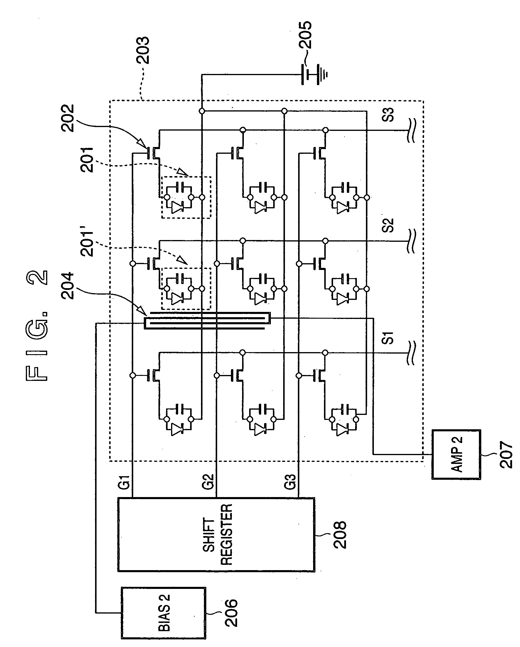
[0068] The second embodiment of the present invention will be described below with reference to FIG. 2 and FIGS. 3A and 3B.

[0069]FIG. 2 is a circuit diagram of a radiation image sensing apparatus of this embodiment. FIGS. 3A and 3B are respectively a plan view and sectional view of building components corresponding to one pixel of the radiation image sensing apparatus; FIG. 3A is a plan view, and FIG. 3B is a sectional view taken along a broken line A-B in FIG. 3A.

[0070] In this embodiment, each first photoelectric conversion element 201 has a PIN structure. Each switch element 202 is formed by a TFT (thin film transistor). The gates of the switch elements 202 are connected to a shift register 208 via gate lines G1 to G3. Output signals from the switch elements 202 are externally output via signal lines S1 to S3.

[0071] A second photoelectric conversion element 204, which has an elongated shape compared to the first photoelectric conversion elements 201 used to read out a normal i...

third embodiment

[0085] The third embodiment of the present invention will be described below with reference to FIG. 4 and FIGS. 5A and 5B.

[0086]FIG. 4 is a circuit diagram of a radiation image sensing apparatus of this embodiment. FIGS. 5A and 5B are respectively a plan view and sectional view of building components corresponding to one pixel of the radiation image sensing apparatus; FIG. 5A is a plan view and FIG. 5B is a sectional view. In this embodiment, a first photoelectric conversion element 401 has an MIS structure, and a switch element 402 comprises a TFT.

[0087] In this embodiment as well, first photoelectric conversion elements 401′ which neighbor a second photoelectric conversion element 403 have an area smaller than those of other first photoelectric conversion element 401.

[0088] The second photoelectric conversion element 403 is connected to a second bias power supply (Bias2) 206, need not be selected by a shift register 208 upon reading out a charge, and is always applied with a bi...


PUM


Abstract

This invention has as its object to realize a radiation image sensing apparatus which can adjust (AEC-controls) the amount of incoming light or dose without requiring high-speed driving. Since a second photoelectric conversion element (108) which is used to detect the total dose of radiation that enters a conversion unit is formed independently of pixels having first conversion elements (101) that are formed in the conversion unit on a single substrate, the need for reading out the outputs from the first conversion elements (101) at high speed for the purpose of adjustment of the dose of incoming radiation can be obviated, and another sensor used to adjust the dose need not be added, thus simplifying the structure of a radiation image sensing apparatus.

Description

FIELD OF THE INVENTION [0001] The present invention relates to a radiation image sensing apparatus and its driving method and, more particularly, to a technique which is suitable for a device that forms an image by radiation, and a device that outputs image information corresponding to incoming radiation. BACKGROUND OF THE INVENTION [0002] In recent years, a demand for “digitization of X-ray image information” has increasingly arisen in the medical field. If such digitization is achieved, a doctor can examine X-ray image information of a patient at an optimal angle in real time, and the obtained X-ray image information can be recorded and managed using a medium such as a magnetooptical disk or the like. Using a facsimile or other communication methods, X-ray image information of a patient can e sent to any hospitals on the globe within a short period of time. [0003] In nondestructive inspection represented by inspection of the interior of an object such as the skeleton of a building...

Claims


Application Information

Patent Timeline
Patent Type & Authority Applications(United States)
IPC IPC(8): H04N5/235H04N5/32H04N5/355H04N5/3745
CPCG01T1/2018H04N5/2351H04N5/3745H04N5/35563H04N5/32H04N23/71H04N25/585H04N25/77
Inventor KOBAYASHI, ISAOMORISHITA, MASAKAZUMOCHIZUKI, CHIORITSUJII, OSAMU
Owner CANON KK
Why Eureka
Try Eureka