

Method for operating fuel cell, fuel cell, and mobile device and mobile phone using same
- Summary
- Abstract
- Description
- Claims
- Application Information
AI Technical Summary
Benefits of technology
Problems solved by technology
Method used
Image

Examples
first embodiment
(First Embodiment)
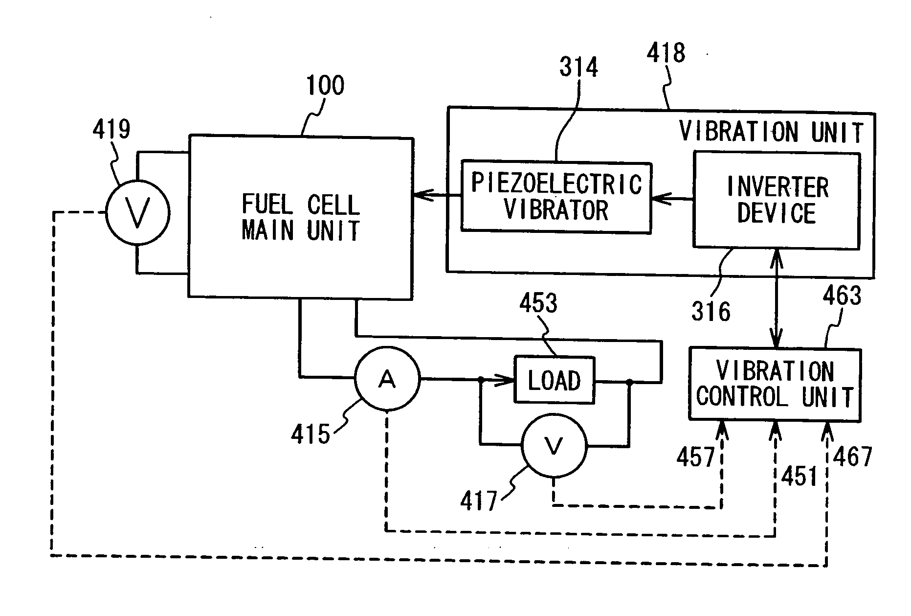
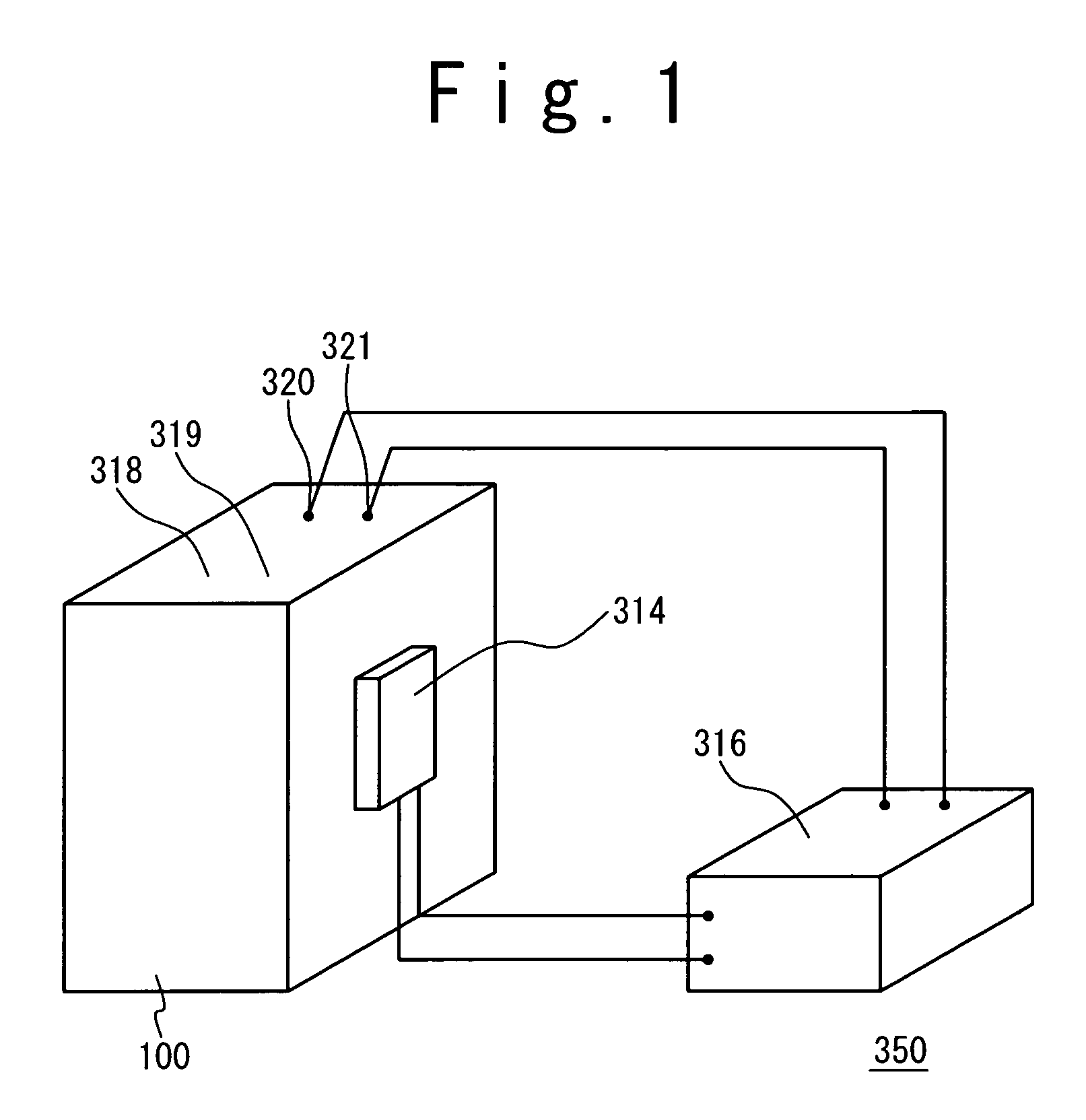
[0058]FIG. 1 is a diagrammatic view showing a configuration of a fuel cell of this embodiment according to the present invention. This fuel cell 350 includes a fuel cell main unit 100, an inverter device 316 and a piezoelectric vibrator 314, and the piezoelectric vibrator 314 as a vibration generating unit. The fuel cell main unit 100 has the four terminals of a first plus terminal 318, a first minus terminal 319, a second plus terminal 320 and a second minus terminal 321. The first plus terminal 318 and the first minus terminal 319 are the terminals so that it is connected to an external circuit. On the other hand, the second plus terminal 320 and the second minus terminal 321 are designed such that the fuel cell main unit 100 and the piezoelectric vibrator 314 are electrically connected through the inverter device 316 to each other, as shown in FIG. 1. A current flowing between the first plus terminal 318 and the first minus terminal 319, and a current flowing be...
second embodiment
(Second Embodiment)
[0098] In this embodiment, the portable telephone as one of portable information devices using the power supply as the fuel cell including the vibration generating unit is described. Here, portable information devices are exemplified in a portable telephone, a note type of a personal computer and PDA (personal digital assistant).
[0099] Conventionally, there is the portable telephone having a function of reporting an incoming to a user through a vibration caused by a vibrating motor and the like. The portable telephone in this embodiment is characterized in that the above-mentioned vibrating motor is used also as the vibration generating unit.
[0100]FIG. 3A is a sectional view showing a portable telephone as one of portable information devices in this embodiment, and shows only a main portion regarding this embodiment.
[0101] The portable telephone 360 includes an outer body 327 and an inner body 326. As shown in FIG. 3A, a vibration damping material 328 is sandwi...
example
[0108] This embodiment will be described below with reference to FIGS. 1 and 2.
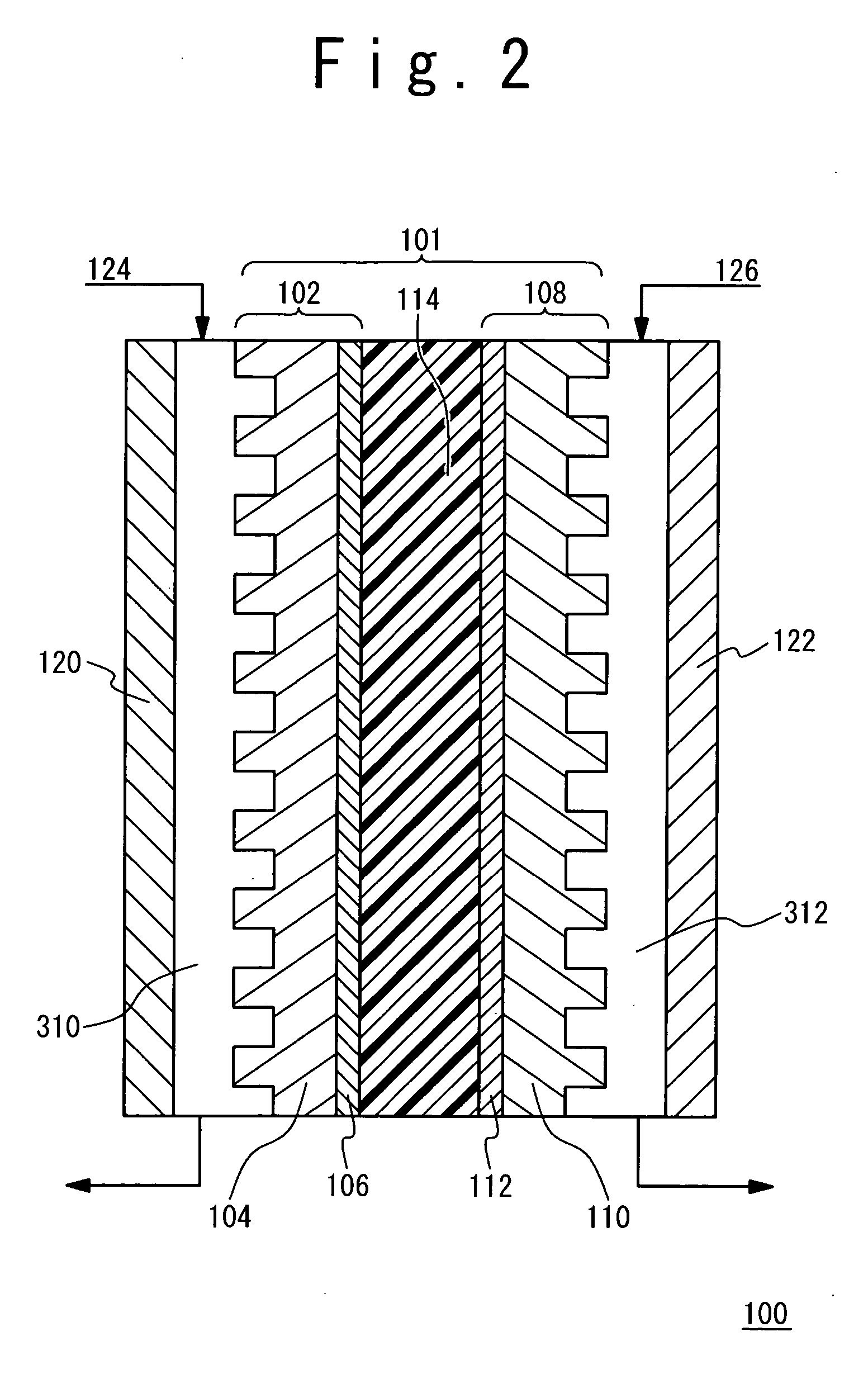
[0109] In FIG. 1, the fuel cell includes the piezoelectric vibrator 314 as the vibration generating unit and the inverter device 316 as the electric power converting (supplying) unit. The inverter device 316 converts apart of the output of the fuel cell main unit 100 into the alternating current, and this alternating current is used to drive the piezoelectric vibrator 314. In FIG. 2, as the catalyst contained in the fuel electrode side catalyst layer 106 and the oxidant electrode side catalyst layer 112, the catalyst supporting carbon micro particles in which an alloy of platinum (Pt) and ruthenium (Ru) that have a particle diameter of 3 to 5 nm was supported at a weight ratio 50% on a carbon micro particles (Denka black; made by Denki Kagaku Kogyo K. K.) . Incidentally, the alloy composition was 50 at % Ru, and the weight ratio of the alloy to the carbon micro particles was 1:1. Then, Swt % NAFION solut...
PUM
 Abstract
Description
Claims
Application Information