
Sheet cutter

Inactive Publication Date: 2005-12-29
CARL JIMUKI
View PDF10 Cites 16 Cited by
  • Summary
  • Abstract
  • Description
  • Claims
  • Application Information

AI Technical Summary

Benefits of technology

[0007] The present invention has been made in light of the disadvantages described above, and it is a first object of the present invention to provide a sheet cutter with a slider installed to a guide rail minimizing abrasion resistance between the slider and the guide rail and enabling to guide the slider in a high linearity on the guide rail. It is further a second object of the present invention to provide the sheet cutter in which a cutter mat can be easily installed to or removed from a fitting groove on a base. It is still further a third object of the present invention to provide the sheet cutter in which a paper-holding ruler can be locked on the base even if it is placed out of the base. Hereinafter described some aspects of the present invention to achieve the above objects.
[0008] In a first aspect, a sheet cutter comprises: a base; a guide rail provided on the base; and a slider provided with a cutter and movably installed on the guide rail, in which each of the slider and the guide rail has either a convex or a concave portion up and down so as to fit each other. Thus constructed, only the convex and concave portions are made abutted each other in cutting processes so as to minimize friction occurred between the slider and the guide rail. The slider can be also moved smoothly along the guide rail in a high linearity.

Problems solved by technology

In this structure, it is not however applicable to lock the paper-holding ruler where the ruler is placed out of the installation table.

Method used


Image

  • Sheet cutter
  • Sheet cutter
  • Sheet cutter

Examples


first embodiment

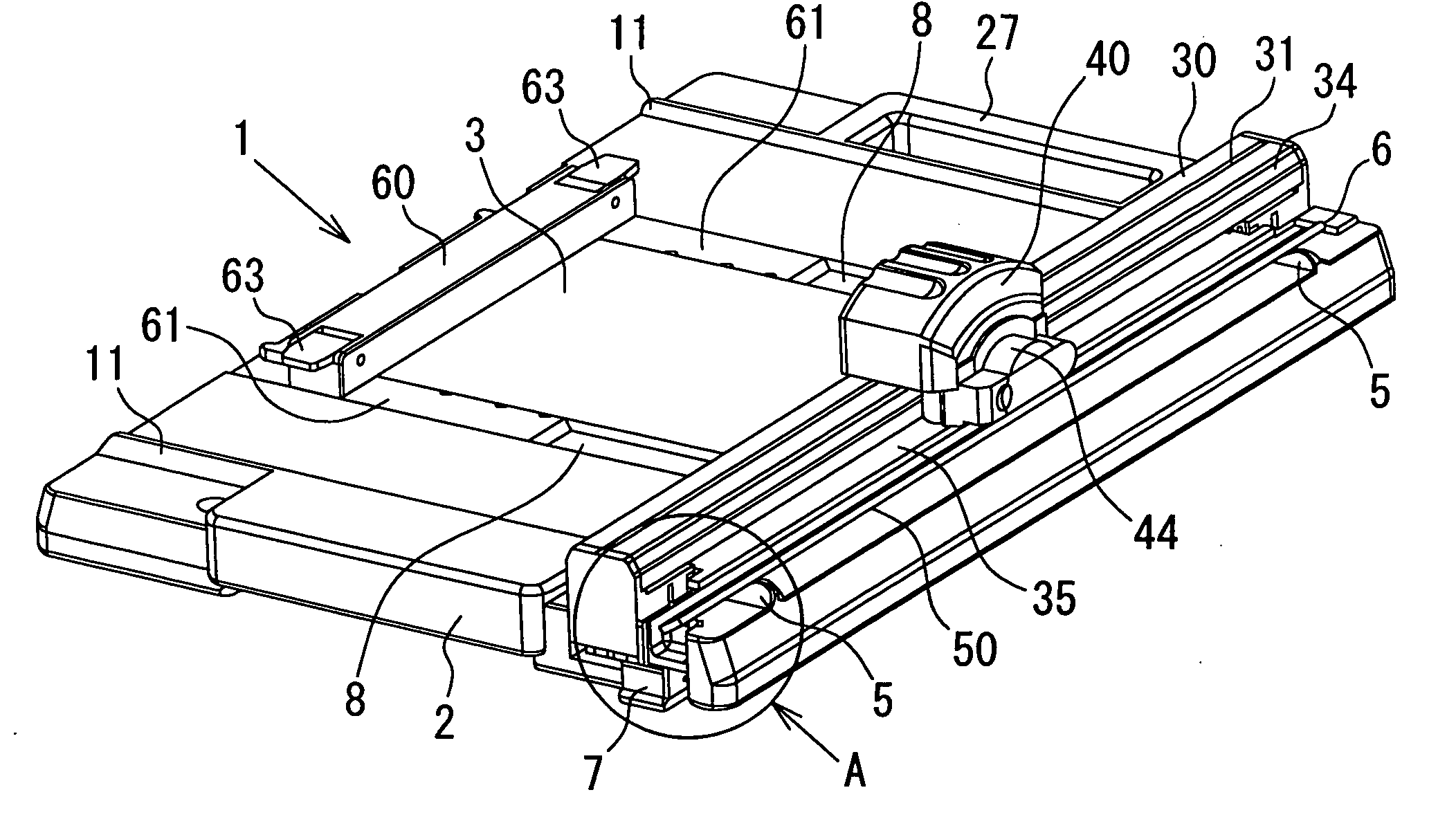
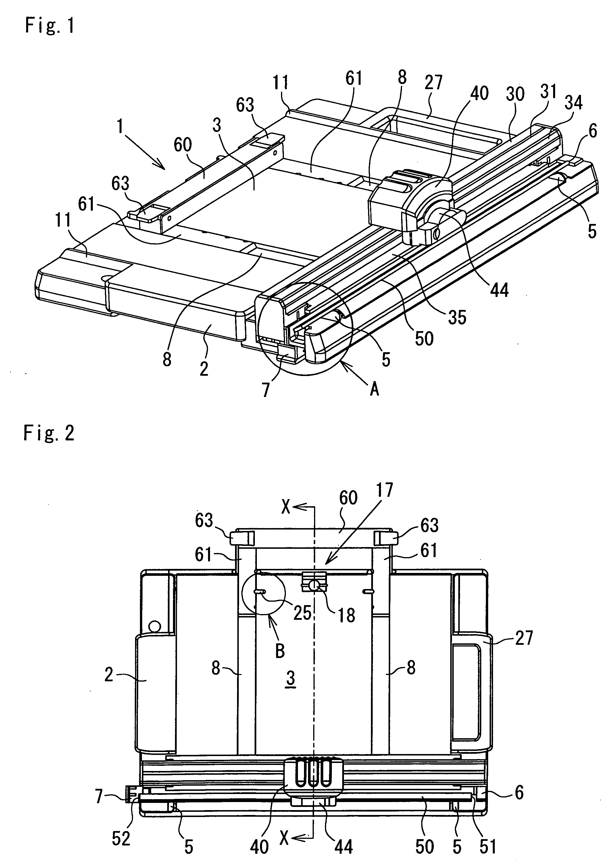
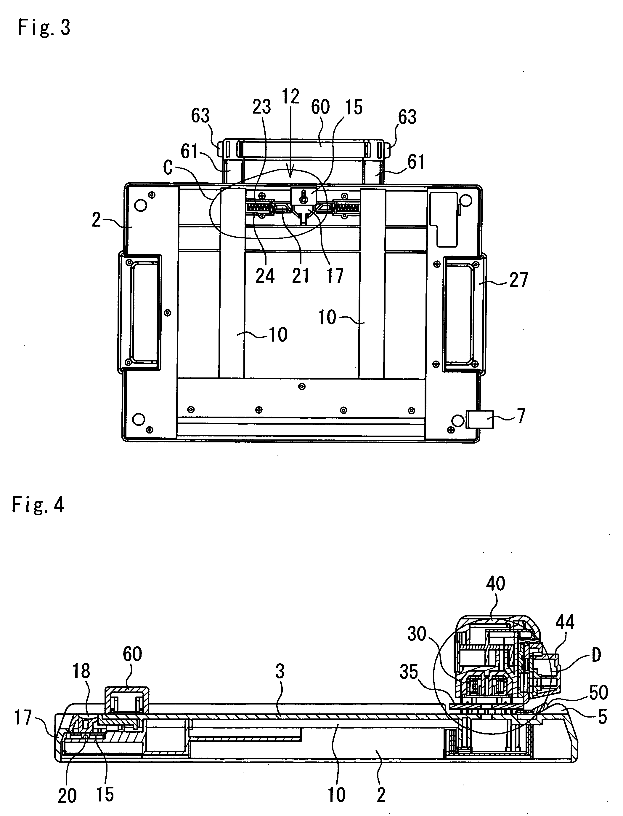
[0056] Next, a positioning means 12 of a first embodiment is hereinafter explained referring to FIGS. 2, 3 and 8. The installation table 3 of the base 2 has hollows 9, which are orthogonal to the guide grooves 8, 8. The projections 25, 25 integrally formed with projection members 24, 24 (hereinafter explained in detail) are sidably fitted to the hollows 9. In case the paper-holding ruler 60 is placed and fixed out of the installation table 3, the projections 25, 25 are engaged with concavities 62, 62 of the foot portions 61, 61. A back surface of the base 2 has a pair of bottom face grooves 10, 10 in position where corresponding to the guide grooves 8, 8. By fixing the foot portions 61, 61 of the paper-holding ruler 60 in the bottom face grooves 10, 10, the paper-holding ruler 60 can be positioned and fixed at a given place.

[0057] The positioning means 12, as shown in FIG. 9, comprises: the pair of projection members 24, 24 arranged in a pair of projection guiding-portions 13, 13 fo...

second embodiment

[0062] Next, the positioning means of another embodiments are still explained hereinafter, mainly focusing on structures of foot portions and projections. In the positioning means, as shown in FIG. 10, one end portions of plate springs 70, 70 are fastened with screws 73, 73 to sides 10A, 10A of the bottom face grooves 10, 10 formed on the back of the installation table 3. The plate springs 70, 70 have curvatures 71, 71 curved toward the guide grooves 8, 8. The curvatures 71, 71 project toward the guide grooves 8, 8 through openings 10B, 10B to engage with concavities 62, 62 on the foot portions 61, 61. The other ends of the plate springs 70, 70, plate spring end portions 72, 72, are movably retained to stowing portions 74, 74 formed on the sides 10A, 10A of the bottom face grooves 10, 10.

[0063] For positioning and fixing the paper-holding ruler 60 in the second embodiment, the steps needed to be taken are: 1] transferring the foot portions 61, 61 along the guide grooves 8, 8 from th...

third embodiment

[0064] In the positioning means, as shown in FIG. 11, one ends of plate springs 70A, 70A are fastened with a screw 73A on the back of foot portions 61A, 61A, for example, on sides 64A, 64A of the foot portions 61A, 61A. The plate springs 70A, 70A have curvatures 71A, 71A curved toward the installation table 3. The curvatures 71A, 71A project toward openings 64B, 64B so as to engage concavities 62A, 62A on the installation table 3. The other ends of the plate springs 70A, 70A, plate spring end portions 72A, 72A, are movably retained to stowing portions 74A, 74A formed on the sides 64A, 64A of the foot portions 61A, 61A.

[0065] For positioning and fixing the paper-holding ruler 60 in the third embodiment, the steps needed to be taken are: 1) transferring the foot portions 61A, 61A along the guide grooves 8, 8 from the state where the curvatures 71A, 71A are placed out of the concavities 62A, 62A as shown in FIG. 11B to the state where the curvatures 71A, 71A are placed facing with the ...


PUM

PropertyMeasurementUnit
Widthaaaaaaaaaa
Frictionaaaaaaaaaa

Abstract

Sheet cutter minimizing friction occurred between a slider and a guide rail while transferring the slider along the guide rail in a high linearity. Each of the slider and the guide rail has either a convex or a concave portion up and down to fit each other. In cutting processes only the convex and concave portions are made abutted each other contributing to minimization of the friction and smooth transferability of the slider in a high linearity.

Description

[0001] BACKGROUND OF THE INVENTION [0002] 1. Field of the Invention [0003] This invention relates to cutters for sheet material mainly papers, and more particularly, to a sheet cutter cutting the sheet material by positioning thereof by means of a paper-holding ruler. [0004] 2. Description of the Related Art [0005] Japanese Patent Application Laid-Open No 11-33978 (hereinafter D1) discloses a sheet cutter in which a slider is movably installed to a guide rail T-shaped in section and provided on a base in such a manner that both a guide groove and a guide surface formed on a guide member of the slider are made fit to the guide rail. Japanese Patent Application Laid-Open No. 6-262586 (hereinafter D2) further relates to a sheet cutter for paper and discloses that a fitting groove for a cutter sheet is formed parallel with a rail provided on a base, and a cutter sheet presser is removably provided at the end of the fitting groove contributing to an easy exchange of the cutter sheet. Jap...

Claims


Application Information

Patent Timeline
IPC IPC(8): B26D1/04B26D1/18B26D1/20B26D7/00B26D7/20
CPCB26D1/045B26D1/185B26D2007/0087B26D7/0006B26D7/20B26D1/205Y10T83/7507Y10T83/8822
Inventor SHIMIZU, FUMIONAKAMURA, TOMOYOSHIISHIHARA, MUNEYUKI
Owner CARL JIMUKI
Features
  • Generate Ideas
  • Intellectual Property
  • Life Sciences
  • Materials
  • Tech Scout
  • Unparalleled Data Quality
  • Higher Quality Content
  • 60% Fewer Hallucinations
Learn More