Method and apparatus for instrument transformer reclassification

a transformer and instrument technology, applied in the field of system and method for measuring the power parameter on a high voltage power line, can solve the problems of large and expensive instrument transformers for installation on high voltage power lines, such as those used for protective relaying and metering, and the replacement of instrument transformers is therefore very costly in terms of capital costs, so as to improve the accuracy of or correct the measurement

Inactive Publication Date: 2005-12-29
POWER MEASUREMENT LTD
View PDF38 Cites 60 Cited by
  • Summary
  • Abstract
  • Description
  • Claims
  • Application Information

AI Technical Summary

Problems solved by technology

Instrument transformers for installation on high voltage power lines, which may include those transformers used for protective relaying and metering, are large and expensive.
For instance, instrument transformers for installation on 230 kV lines may cost more than $100,000 U.S. each.
Replacement of instrument transformers is thus very costly in terms of capital costs.
It is also very costly to replace instrument transformers due to the necessity to power down the power line while doing so.
The large size of the instrument transformers also means that installation / removal and transportation costs are high.
These instrument transformers are typically designed to operate during large fault currents or voltages and are therefor not optimized for accuracy at normal currents and voltages.
For example a relaying current transformer may have a large magnetic core and high core losses.
When instrument transformers optimized for metering applications are provided in an installation, they may be subject to degradation in accuracy over time.
This may be due to magnetization from surge voltages or currents, insulation breakdown, degradation due to environmental stresses, etc.
It is therefor common in legacy installations to have inaccuracies in the measurement of voltage, current and therefore power flow due to the degradation and / or inherent inaccuracy of the installed instrumentation.

Method used


Image

  • Method and apparatus for instrument transformer reclassification
  • Method and apparatus for instrument transformer reclassification
  • Method and apparatus for instrument transformer reclassification

Examples


Embodiment Construction

[0022] Herein, the phrase “coupled with” is defined to mean directly connected to or indirectly connected through one or more intermediate components. Such intermediate components may include both hardware and software based components. Further, to clarify the use in the pending claims and to hereby provide notice to the public, the phrases “at least one of , , . . . and ” or “at least one of , , . . . , or combinations thereof” are defined by the Applicant in the broadest sense, superceding any other implied definitions herebefore or hereinafter unless expressly asserted by the Applicant to the contrary, to mean one or more elements selected from the group comprising A, B, . . . and N, that is to say, any combination of one or more of the elements A, B, . . . or N including any one element alone or in combination with one or more of the other elements which may also include, in combination, additional elements not listed.

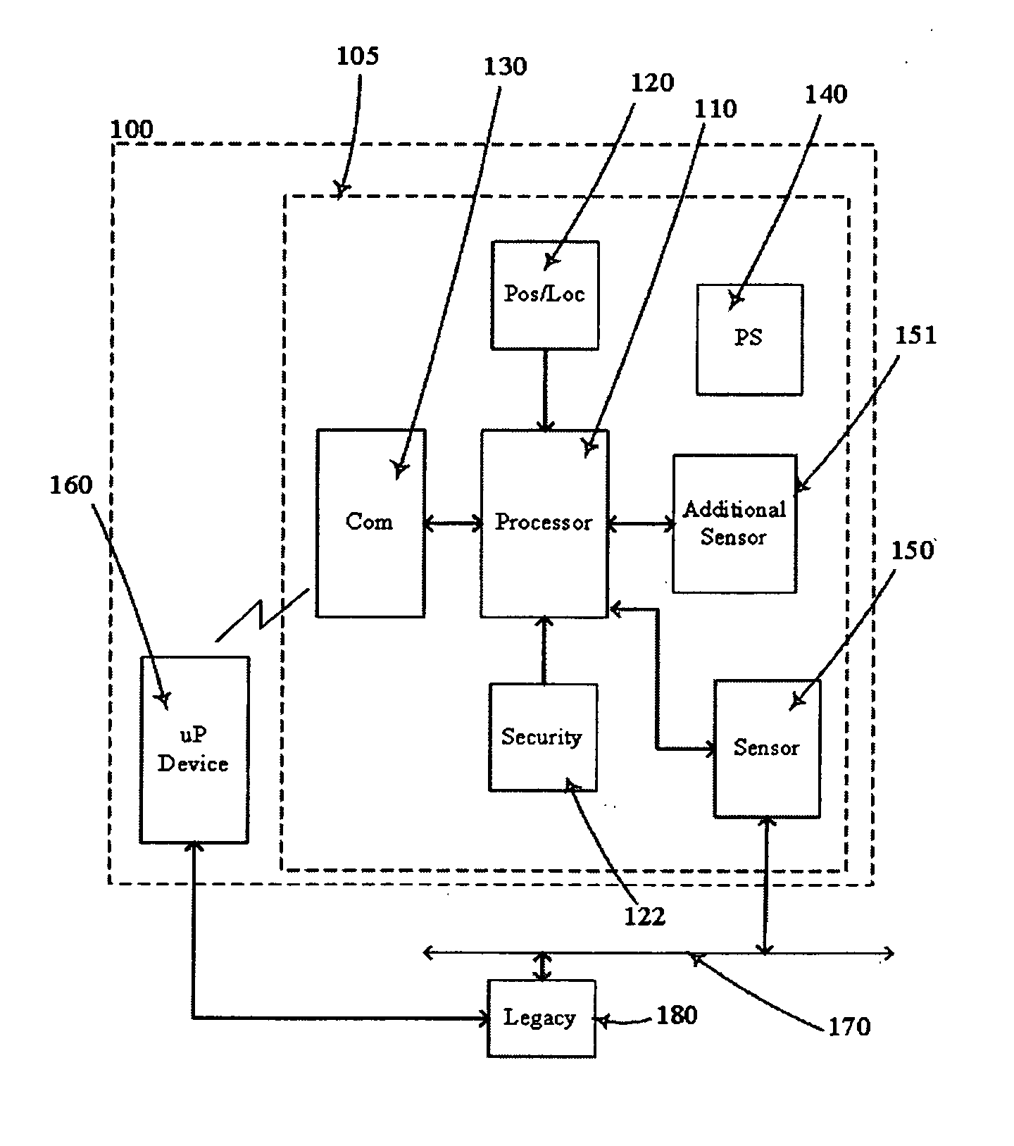
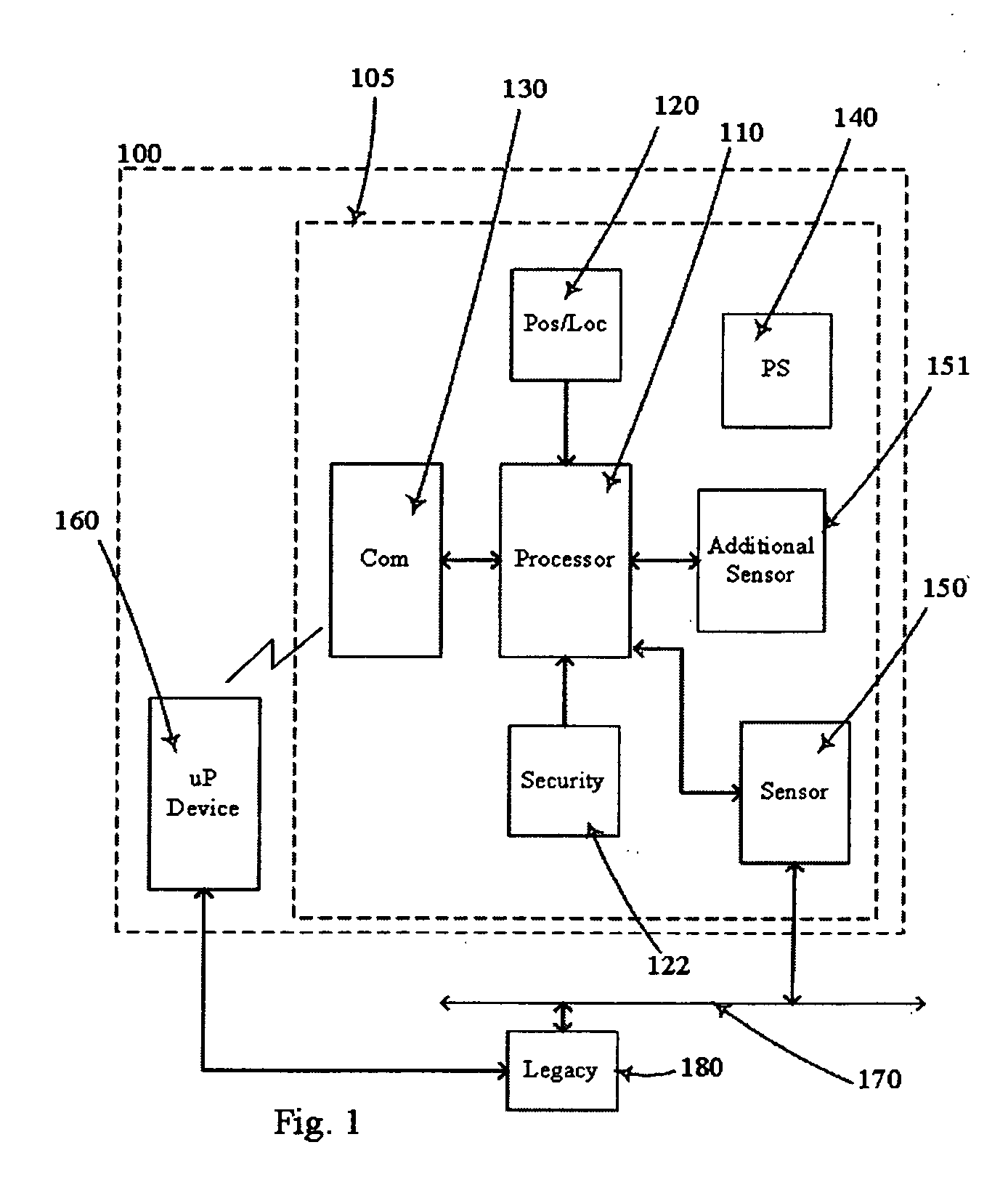
[0023] Examples of the present invention provide systems and...


PUM


Abstract

Systems and methods for reclassifying instrument transformers. A line mounted device that includes a sensor that can be attached to a power line. The line mounted device generates data or representations of the power parameters of the power line. A processor in the line mounted device produces modified representations of the power parameters that are transmitted wirelessly to a microprocessor based device. The microprocessor based device also receives second representations of the power parameters from legacy instrumentation. Compensation data is produced based on the modified representations from the line mounted device and the second representations from the legacy instrumentation. The compensation data can be used to compensate or correct the representations of the power parameters from the legacy instrumentation even after the line mounted device is no longer attached to the power line.

Description

CROSS-REFERENCE TO RELATED APPLICATIONS [0001] This application is a continuation in part under 37 C.F.R § 1.53(b) of U.S. patent application Ser. No. 10 / 877,742, filed Jun. 25, 2004 (pending), the entire disclosure of which is hereby incorporated by reference.BACKGROUND OF THE INVENTION [0002] 1. The Field of the Invention [0003] The present invention relates to systems and methods for measuring a power parameter on a high voltage power line. More particularly, the present invention relates to systems and methods for improving the accuracy of measurement of power parameters on a high voltage power line including compensating for inaccuracies in the output of instrument transformers designed for connection to power lines of 10 kV or higher. [0004] 2. Background and Relevant Art [0005] Instrument transformers for installation on high voltage power lines, which may include those transformers used for protective relaying and metering, are large and expensive. This is especially true at...

Claims


Application Information

Patent Timeline
Patent Type & Authority Applications(United States)
IPC IPC(8): G01R15/18G01R21/00G01R21/133G01R35/00
CPCG01R15/18G01R21/133H01F38/28G01R35/02G01R35/007
Inventor DOIG, PAUL E.HANCOCK, MARTIN A.GUNN, COLIN N.FORTH, J. BRADFORDCOWAN, PETER C.LIGHTBODY, SIMON H.COCHRANE, MARCIE L.HARDING, STEWART J.LOEWEN, DANIEL N.
Owner POWER MEASUREMENT LTD
Why Eureka
Try Eureka