Multi-venturi tube fuel injector for gas turbine combustors

a fuel injector and gas turbine technology, applied in the direction of machines/engines, mechanical equipment, lighting and heating apparatus, etc., can solve the problems of catalyst inlet thermal or velocity mal-distribution deleterious, catalyst not working optimally, etc., to enhance fuel/air mixing, improve fuel circuit, and eliminate flame-holding problems

Inactive Publication Date: 2006-01-05
GENERAL ELECTRIC CO
View PDF2 Cites 23 Cited by
  • Summary
  • Abstract
  • Description
  • Claims
  • Application Information

AI Technical Summary

Benefits of technology

[0004] In accordance with the preferred aspect of the present invention, there is provided in combination in a combustor, a flow conditioner, a venturi configuration having a diffuser with multiple sides and an improved fuel circuit. The flow conditioner may be of the type described and illustrated in co-pending U.S. patent application Ser. No. 10 / 648,203 filed Aug. 27, 2003, the disclosure of which is incorporated herein by reference. In addition to the flow conditioner, multiple venturi tubes having a frustum-like cross-sectional configuration are provided to enhance fuel / air mixing, to afford uniform distribution of the fuel / air, velocity and temperature at the catalyst inlet, and to eliminate flame-holding issues. The venturi configuration eliminates recirculation regions, i.e., flow gaps between the venturis in the exit planes and downstream thereof, as well as the potential for flame-holding. The venturis have a three body construction to improve fuel distribution among the various venturis and also to improve mechanical durability by thermo-shielding of the brazed joints of the construction. The venturi fuel circuit provides a secondary plenum between the main fuel plenum surrounding the venturis defined between spaced axial forward and aft walls and fuel supply inlets to the converging inlet of the venturis. By providing a secondary plenum in each venturi, the plane of fuel intake into the plenum is separated from the plane of fuel injection into the venturi by a maximum available distance. Also cold fuel flow is directed along the cold side of the fuel plenum thereby minimizing thermal stress at the front and aft plate brazed joints.

Problems solved by technology

Absent either one of these factors, the catalyst does not function optimally.
That is, mixing in that cross-sectional region is limited.
For example, if a region of flow has a high temperature or velocity in comparison to the remaining flow, the thermal or velocity mal-distribution will deleteriously appear at the catalyst inlet.

Method used


Image

  • Multi-venturi tube fuel injector for gas turbine combustors
  • Multi-venturi tube fuel injector for gas turbine combustors
  • Multi-venturi tube fuel injector for gas turbine combustors

Examples


Embodiment Construction

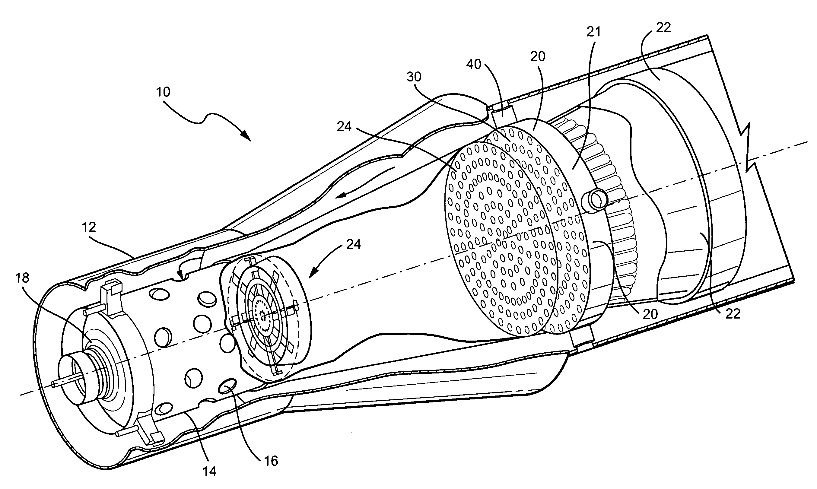
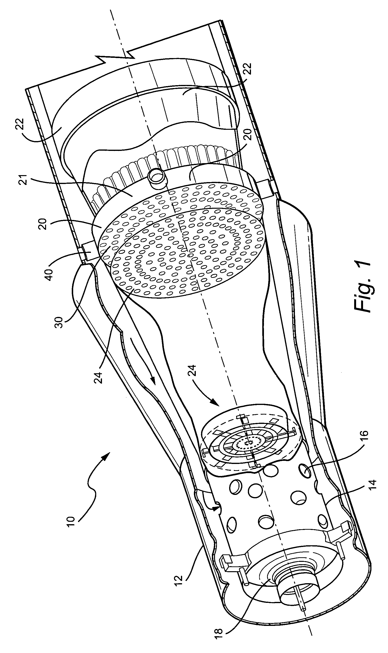
[0014] As will be appreciated a typical gas turbine has an array of circumferentially spaced combustors about the axis of the turbine for burning a fuel / air mixture and flowing the products of combustion through a transition piece for flow along the hot gas path of the turbine stages whereby the energetic flow is converted to mechanical energy to rotate the turbine rotor. The compressor for the turbine supplies part of its compressed air to each of the combustors for mixing with the fuel. A portion of one of the combustors for the turbine is illustrated in FIG. 1 and it will be appreciated that the remaining combustors for the turbine are similarly configured. Smaller gas turbines can be configured with only one combustor having the configuration illustrated in FIG. 1.

[0015] Referring to FIG. 1 a combustor, generally designated 10, includes a preburner section 12 having an interior flow liner 14. Liner 14 has a plurality of holes 16 for receiving compressor discharge air for flow i...


PUM


Abstract

A combustor for a gas turbine includes a main fuel injector for receiving compressor discharge air and mixing the air with fuel for flow to a downstream catalytic section. The main fuel injector includes an array of venturis each having an inlet, a throat and a diffuser. A main fuel supply plenum between forward and aft plates supplies fuel to secondary annular plenums having openings for supplying fuel into the inlets of the venturis upstream of the throats. The diffusers transition from a circular cross-section at the throat to multiple discrete angularly related side walls at the diffuser exits without substantial gaps therebetween. With this arrangement, uniform flow distribution of the fuel/air, velocity and temperature is provided at the catalyst inlet.

Description

BACKGROUND OF THE INVENTION [0001] The present invention relates to a fuel injector for gas turbine combustors and particularly relates to a multi-venturi fuel injector for catalytic and dry low-NOx applications. [0002] The main components of a combustor for a gas turbine, for example, a catalytic combustor, include (1) a pre-burner which may typically constitute a diffusion style combustor that burns a small fraction of the fuel to elevate air temperature sufficiently to activate the catalyst downstream; (2) a pre-mixer which includes the main fuel injector and accomplishes fuel and air mixing; (3) a catalyst which partially converts the fuel in a flameless reaction in which no NOx is produced; and (4) a burn-out zone which includes homogeneous combustion in a post-catalyst liner of the lean fuel / air mixture flowing from the catalyst which does not generate NOx due to the relatively reduced temperature of the combustion. This type of combustor is capable of generating very low emis...

Claims


Application Information

Patent Timeline
Patent Type & Authority Applications(United States)
IPC IPC(8): F23R3/40
CPCF23R3/40
Inventor DINU, CONSTANTIN ALEXANDRUHU, IRIS ZIQINSTOREY, JAMES MICHAELFARRELL, THOMAS RAYMOND
Owner GENERAL ELECTRIC CO
Why Eureka
Try Eureka