Drum washing machine
a drum washing machine and drum technology, applied in the direction of other washing machines, sustainable buildings, textiles and papermaking, etc., can solve the problems of damaged tub covers, inability to smoothly rotate drums during drum washing machines, and inability to prevent the front wall of the tub from being damaged, so as to prevent the damage of the tub and the effect of reducing vibration
- Summary
- Abstract
- Description
- Claims
- Application Information
AI Technical Summary
Benefits of technology
Problems solved by technology
Method used
Image
Examples
first embodiment
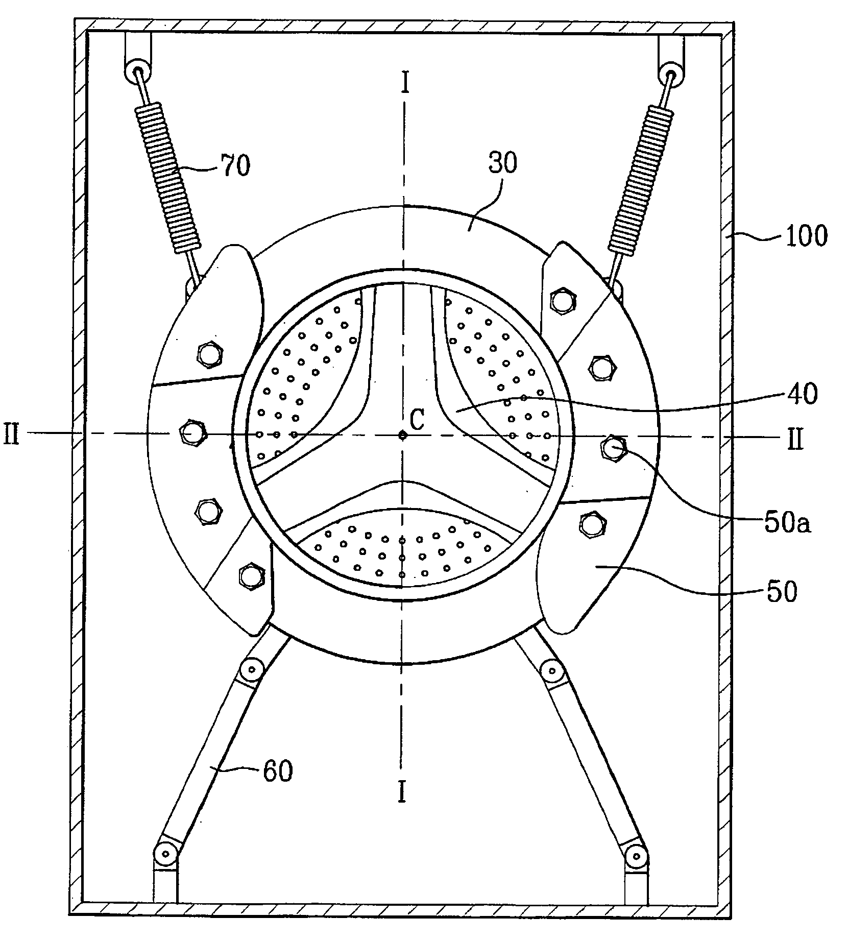
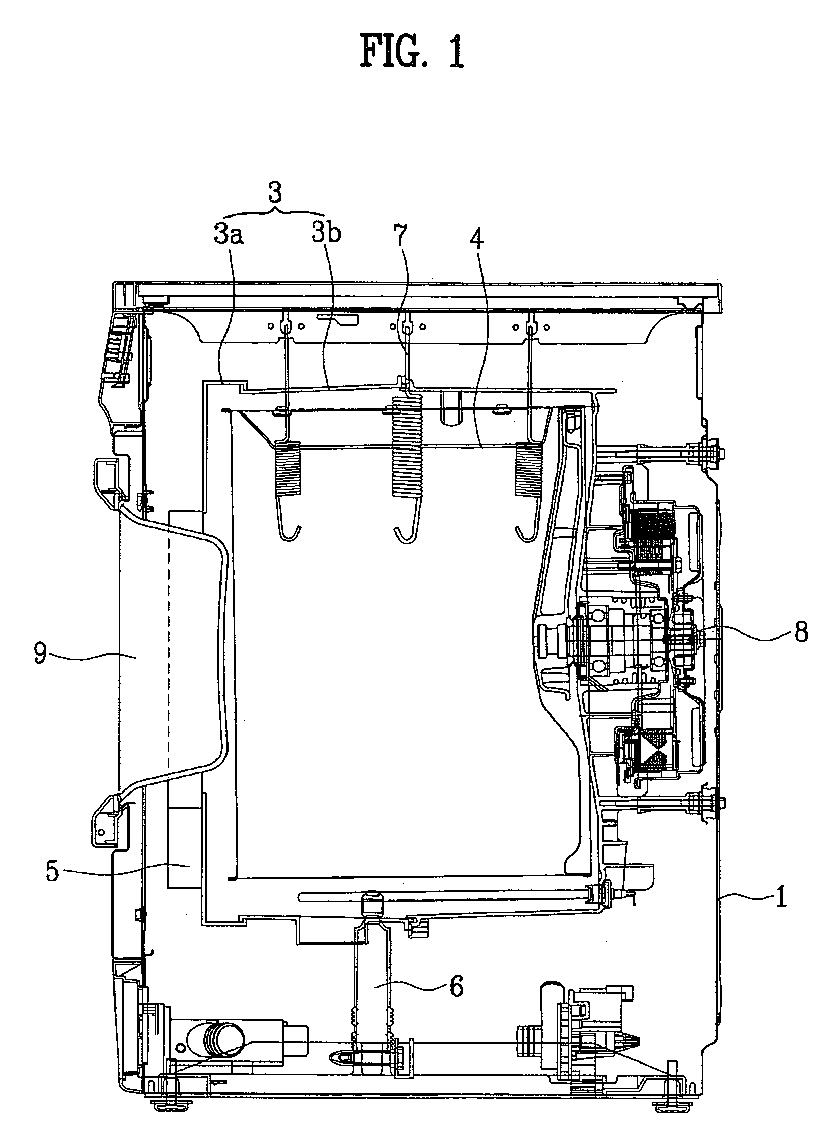
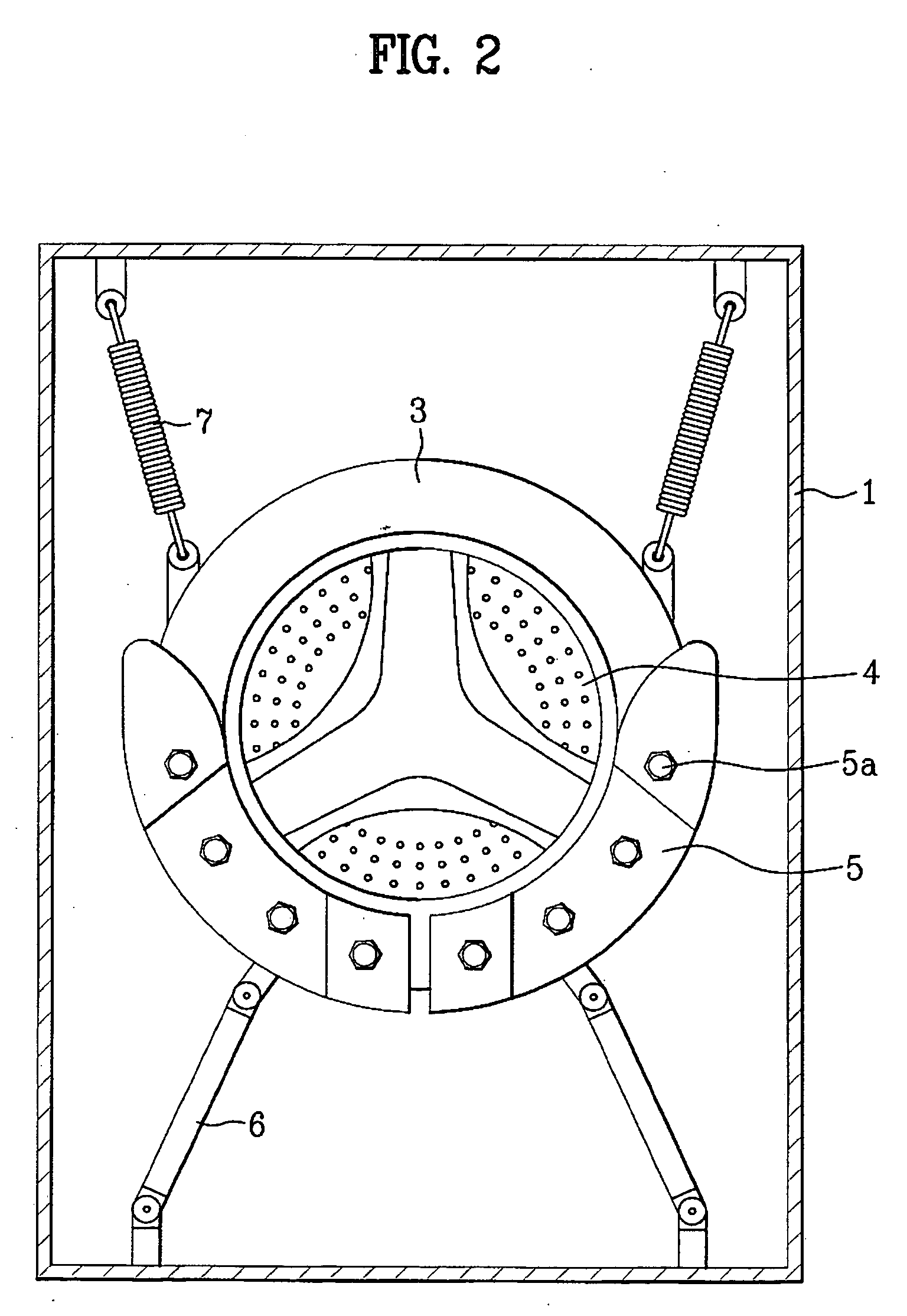
[0046]FIG. 4 illustrates a balance weight mounting structure for mounting balance weights in a drum washing machine in accordance with the present invention. In this case, the drum washing machine includes a cabinet 100, which forms an outer appearance of the drum washing machine, a tub 30 arranged in the cabinet 100 to contain washing water, and a drum 40 rotatably arranged in the tub 30 to carry out a laundry washing function in accordance with rotation of a motor 80 mounted to a rear wall of the tub 30.
[0047] Balance weights 50 are mounted to a front wall of the tub 30 such that the balance weights 50 are symmetrical with respect to a first center line I-I extending vertically through the center c of the front wall of the tub 30 along the front wall of the tub 30. The balance weights 50 are also symmetrical with respect to a second center line II-II extending through the center c of the front wall of the tub 30 in perpendicular to the first center line I-I along the front wall of...
second embodiment
[0049] Meanwhile, FIG. 5 illustrates a balance weight mounting structure for mounting balance weights in a drum washing machine in accordance with the present invention. In this case, balance weights 50 are mounted to the front wall of the tub 30 such that the balance weights 50 are symmetrical with respect to a third center line III-III extending diagonally through the center c of the front wall of the tub 30 along the front wall of the tub 30. The balance weights 50 are also symmetrical with respect to a fourth center line IV-IV extending through the center c of the front wall of the tub 30 in perpendicular to the third center line III-III along the front wall of the tub 30.
[0050] In both the first and second embodiments illustrated in FIGS. 4 and 5, the weight of each balance weight 50 is determined, taking into consideration the weight of the motor 80 mounted to the rear wall of the tub 30. In either embodiment, it is preferred that the total weight of the balance weights 50 be ...
third embodiment
[0056] As shown in FIG. 6, the drum washing machine applied to the present invention includes a cabinet (not shown), which forms an outer appearance of the drum washing machine, a tub 30 arranged in the cabinet to contain washing water, and a drum 40 rotatably arranged in the tub 30 to carry out a laundry washing function in accordance with rotation of a motor (not shown) mounted to a rear wall of the tub 30.
[0057] A suction duct 10 adapted to suck air into the drum 40 and an exhaust duct 20 adapted to exhaust air from the drum 40 are mounted to the tub 30. An air inlet 31 is formed at the tub 30 in order to communicate the tub 30 with the suction duct 10. Balance weights 50 are mounted to a front wall of the tub 30 in such a manner that the front wall of the tub 30 is balanced in weight between positions opposing to each other with respect to the center of the front wall of the tub 30.
[0058] As described above, this drum washing includes the suction duct 10 and exhaust duct 20 for...
PUM
 Abstract
Description
Claims
Application Information
 - R&D
- Intellectual Property
- Life Sciences
- Materials
- Tech Scout
- Unparalleled Data Quality
- Higher Quality Content
- 60% Fewer Hallucinations
Browse by: Latest US Patents, China's latest patents, Technical Efficacy Thesaurus, Application Domain, Technology Topic, Popular Technical Reports.
© 2025 PatSnap. All rights reserved.Legal|Privacy policy|Modern Slavery Act Transparency Statement|Sitemap|About US| Contact US: help@patsnap.com


