
System and method for vehicle defogging condition calculation and control

a vehicle and condition technology, applied in the field of vehicle environmental control systems and methods, can solve the problems of increased cost of purchase, and inability to automatically control the system

Active Publication Date: 2006-01-05
HONDA MOTOR CO LTD
View PDF2 Cites 41 Cited by
  • Summary
  • Abstract
  • Description
  • Claims
  • Application Information

AI Technical Summary

Benefits of technology

[0007] The present invention is directed toward a method and apparatus to prevent fogging conditions from occurring in a vehicle, and for responding to fogging conditions that do occur in a vehicle.
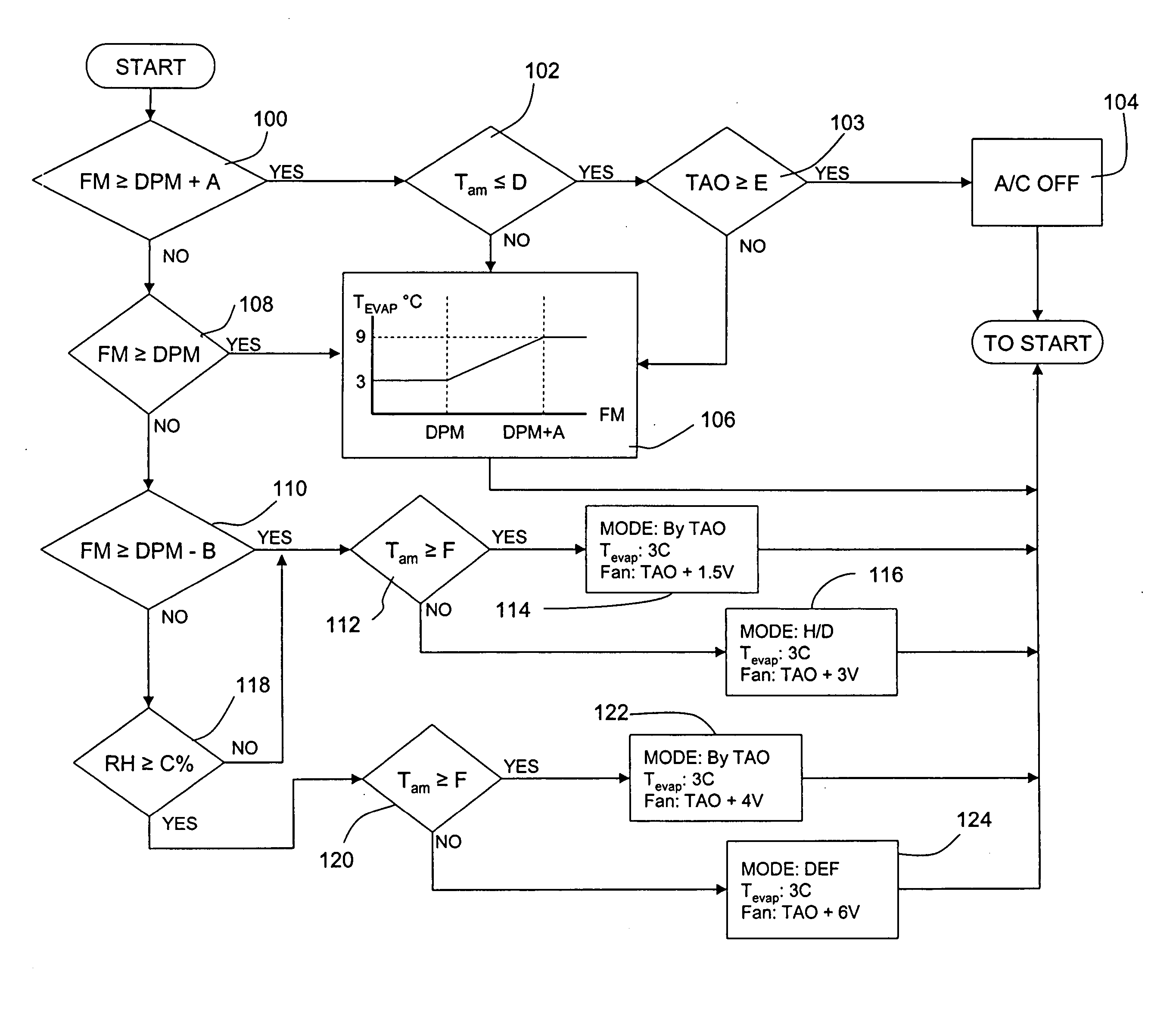
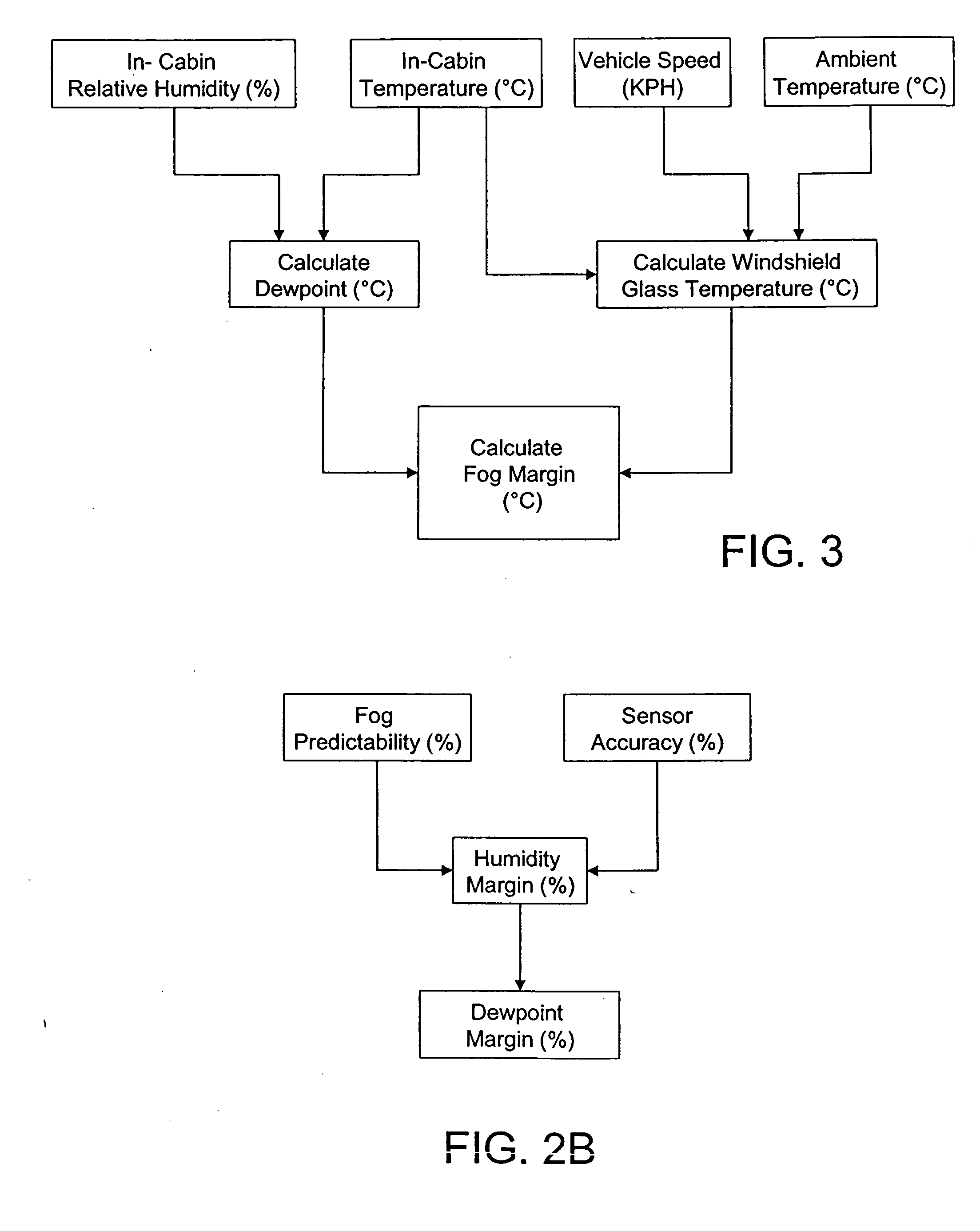
[0010] In further accordance with the present invention, a method and apparatus for controlling a vehicle HVAC system to automatically defog a windshield glass and to prevent fogging or condensation on the windshield glass. The ambient air temperature and vehicle speed are measured and used to determine a windshield glass temperature. The in-cabin air temperature and relative humidity are measured and used to determine a dewpoint. A dewpoint margin is calculated to compensate for sensor accuracy and fog predictability. The fog margin, which is based upon calculated windshield glass temperature and dewpoint, is calculated and used, in conjunction with the dewpoint margin, to control the HVAC system to anticipate potential fogging conditions and to scale the intensity of the HVAC system response in accordance with the severity of fogging conditions.

Problems solved by technology

Naturally, such remedial measures, which primarily consist of activating a vehicle heating, ventilation, and air conditioning (HVAC) system into a defrost mode of operation, are employed after a fogging condition has developed, and typically require some time to alleviate the fogging condition.
As will be appreciated, such systems are not suitable for automatic control, and do not anticipate impending fogging conditions.
Unfortunately, such automated systems require additional sensors, which are expensive to purchase and require significant amounts of labor to install and electrically connect to the HVAC controller.

Method used


Image

  • System and method for vehicle defogging condition calculation and control
  • System and method for vehicle defogging condition calculation and control
  • System and method for vehicle defogging condition calculation and control

Examples


Embodiment Construction

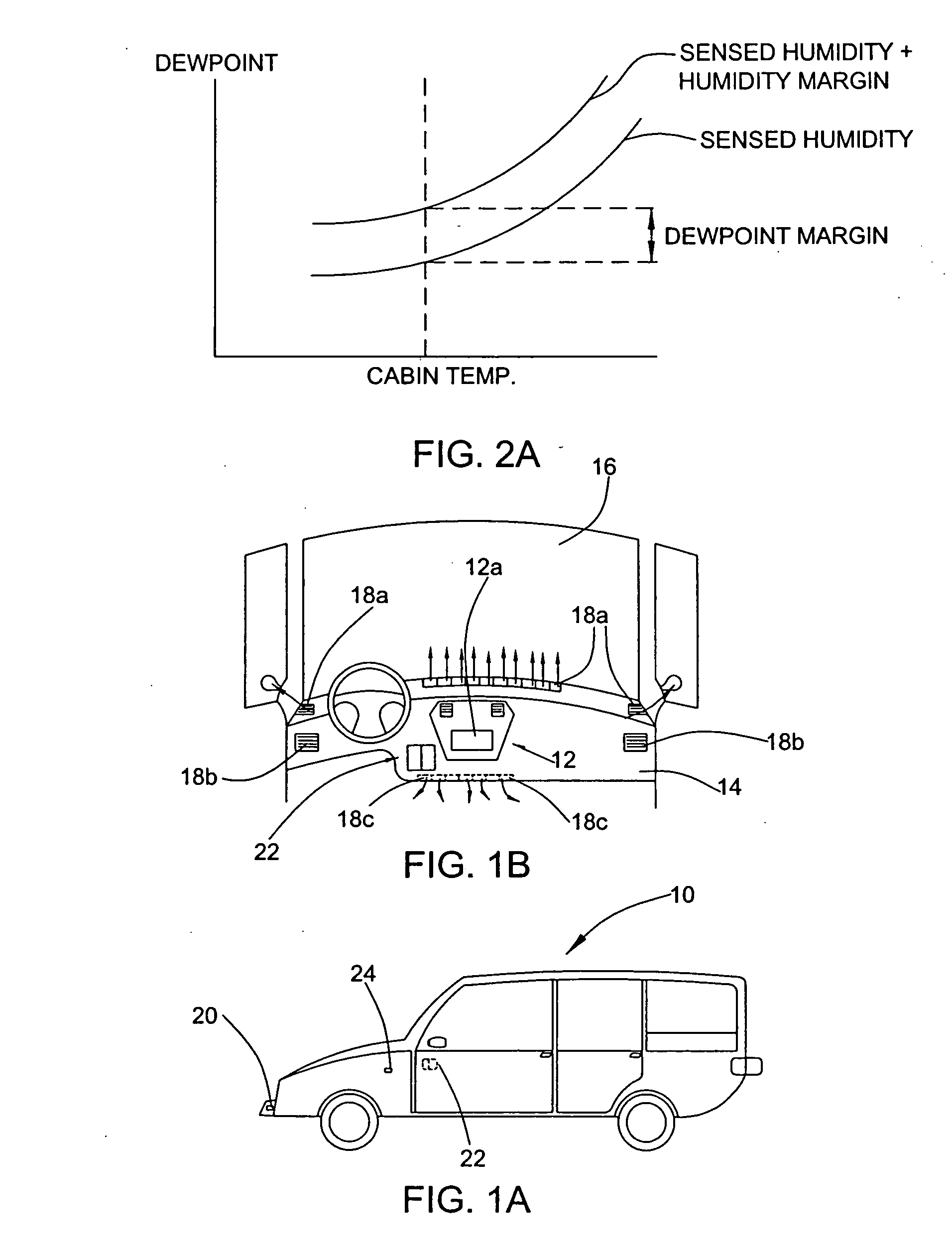
[0019] With reference to FIGS. 1A-1B, a vehicle 10 incorporating the automatic defogging system of the present invention is schematically illustrated. As will be appreciated, the automatic defogging system is incorporated into the vehicle's computer based heating, ventilation, and air conditioning (HVAC) system, which preferably includes several modes of operation. The automatic defogging system, as part of the HVAC system and as described hereinafter, is intended to be operational when the HVAC system is operated in an automatic mode of operation and to operate seamlessly as one step or sequence of steps during the automatic mode of operation.

[0020] In such an automatic mode, the user sets a desired cabin temperature and the computer or controller of the HVAC system makes necessary calculations, in response to signals from various sensors and one or more predefined programs defining operational characteristics of the HVAC system, tuned to the inherent physical characteristics of t...


PUM


Abstract

A method and apparatus for controlling a vehicle HVAC system to automatically defog a windshield glass and to prevent fogging or condensation of the windshield glass. The ambient air temperature and vehicle speed are measured and used to determine a windshield glass temperature. The in-cabin air temperature and relative humidity are measured and used to determine a dewpoint. An dewpoint margin is calculated to compensate for sensor accuracy and fog predictability. A fog margin, which is based upon calculated windshield glass temperature and dewpoint, is calculated and used, in conjunction with the dewpoint margin, to control the HVAC system to anticipate potential fogging conditions and to scale the intensity of the HVAC system response based upon the severity of fogging conditions.

Description

BACKGROUND OF THE INVENTION [0001] 1. Field of the Invention [0002] The present invention relates to vehicle environmental control systems and methods and, more particularly, toward methods and systems for automatically sensing fogging conditions, and instituting appropriate measures to prevent fogging and to remove window fog should fog be present. [0003] 2. Description of Related Art [0004] In conventional automobile control systems, application of remedial measures to combat fogging of the vehicle windows is manually instituted by the vehicle passengers. Naturally, such remedial measures, which primarily consist of activating a vehicle heating, ventilation, and air conditioning (HVAC) system into a defrost mode of operation, are employed after a fogging condition has developed, and typically require some time to alleviate the fogging condition. As will be appreciated, such systems are not suitable for automatic control, and do not anticipate impending fogging conditions. [0005] I...

Claims


Application Information

Patent Timeline
IPC IPC(8): B60H1/00
CPCB60H1/00785B60H1/00828B60H1/00814
Inventor ERRINGTON, BRADLEY C.KANEMARU, JUNICHI
Owner HONDA MOTOR CO LTD
Learn More