
Connecting mechanism

a technology of connecting mechanism and connecting rod, which is applied in the direction of couplings, sealing/packing, and wellbore/well accessories, etc., can solve the problems of increasing the price of the connecting rod, requiring a relatively large design effort, and requiring considerable design effort, so as to achieve secure and stable connection of parts and simple design

Inactive Publication Date: 2006-01-05
ONESUBSEA IP UK LTD
View PDF5 Cites 13 Cited by
  • Summary
  • Abstract
  • Description
  • Claims
  • Application Information

AI Technical Summary

Benefits of technology

[0006] For this reason, the invention takes as a basis the object of improving a connecting mechanism of the type mentioned at the beginning, to the effect that, with simple design means without additional fastening or tightening devices, a secure and stable connection of parts is ensured even when these parts are only partially inserted into one another.

Problems solved by technology

This requires a relatively large design effort and is essentially only implementable for parts that are entirely inserted into one another.
For example, in order to insert two parts only partially into one another, further design measures must be taken with regard to the connecting mechanism according to U.S. 2001 / 0011592 A1, which measures require considerable design effort and which would raise the price of the connecting mechanism.

Method used


Image

  • Connecting mechanism
  • Connecting mechanism
  • Connecting mechanism

Examples


Embodiment Construction

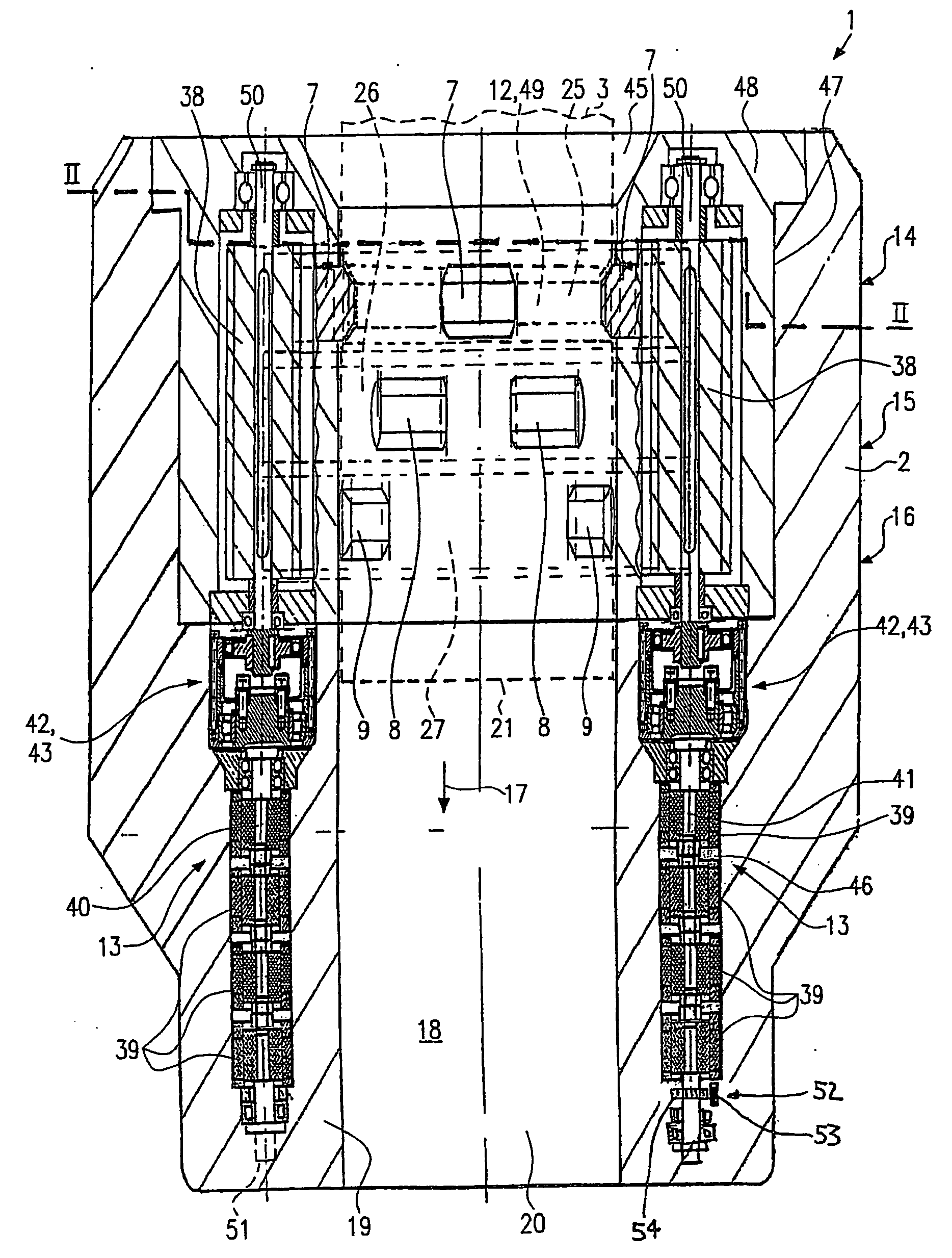
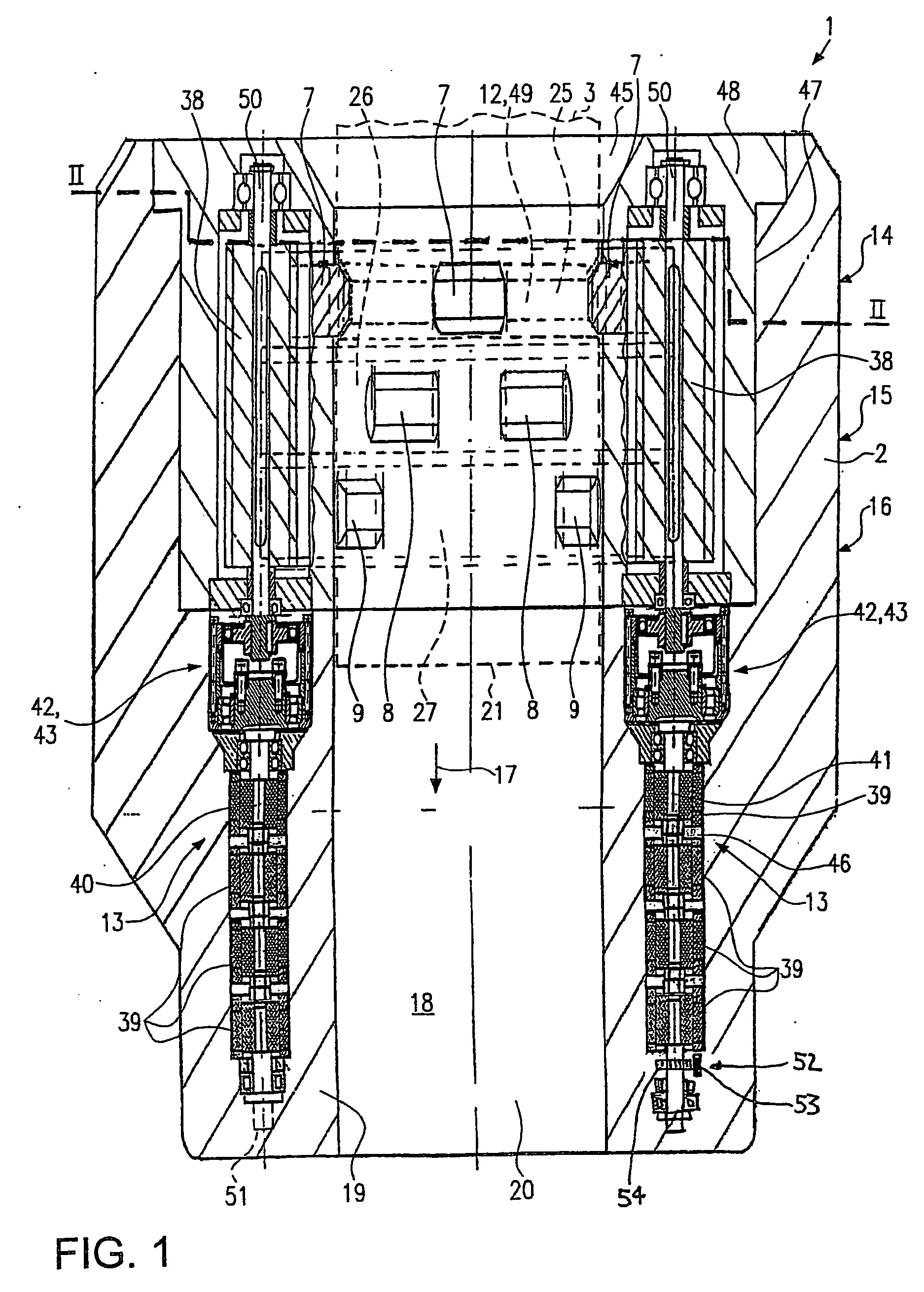
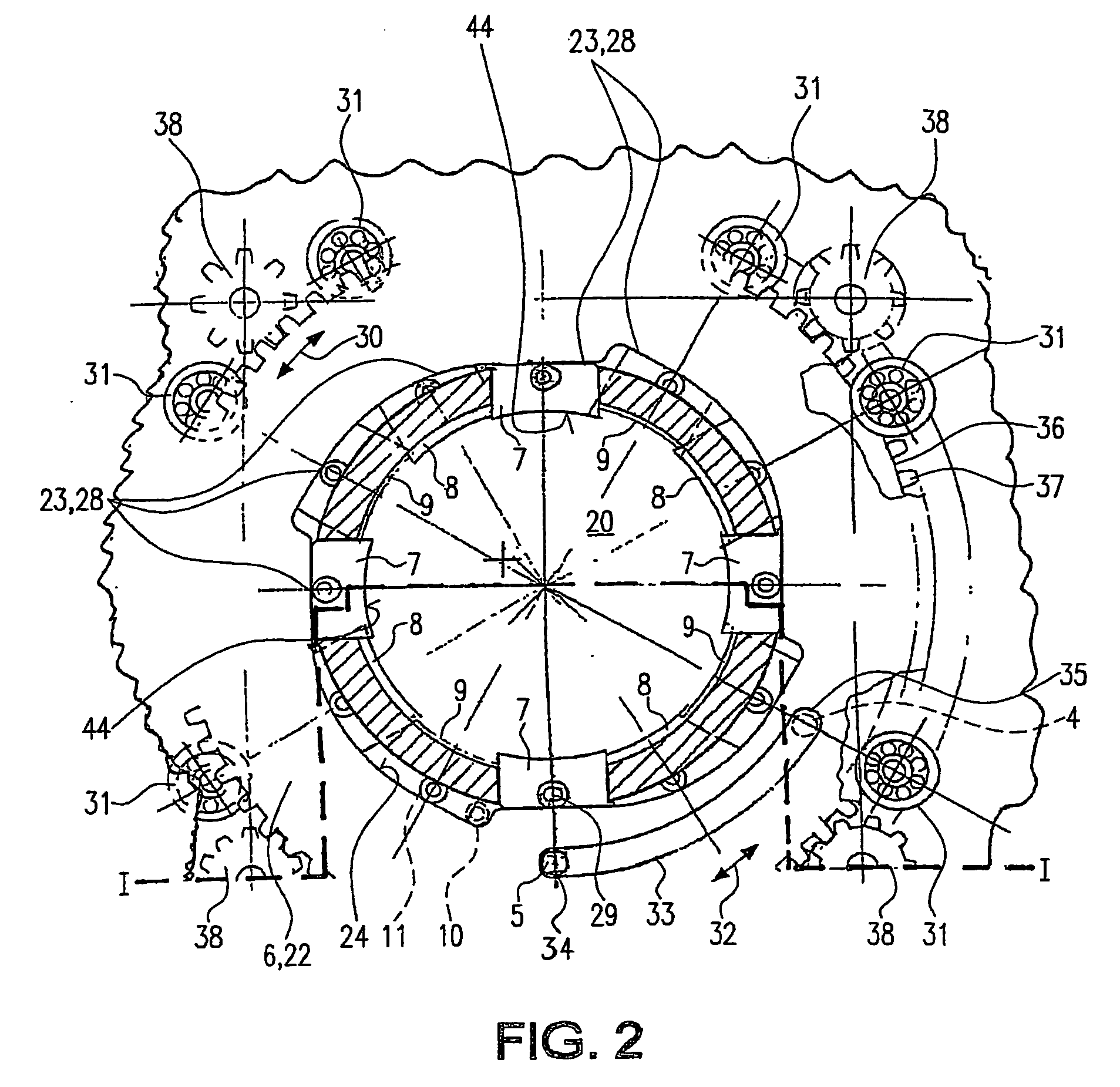
[0042]FIG. 1 shows an embodiment of a connecting mechanism 1 according to the invention with a cut along the line I-I from FIG. 2. The connecting mechanism 1 is held in a tubular part 2, which, for example, can bring about a connection from an upper end of a stack of BOPs (blowout preventers) to a so-called riser.

[0043] The tubular part 2 presents a longitudinal bore hole 20, in which a tubular second part 3 can be inserted from an insertion end 45. The other part 3 is inserted into part 2 so far that it is arranged with its free end 21 roughly in the center of part 2 according to FIG. 1.

[0044] In a wall 19 of part 2, in the embodiment shown, four retainer bore holes 46 are formed in which driving devices 13 are inserted. The retainer bore holes 46 can also be formed from an annulus.

[0045] Above the retainer bore hole 46, part 2 presents a ring clearance zone 47, which is open towards the longitudinal bore hole 20. An insertion sleeve 48 is detachably placed in this. In particula...


PUM


Abstract

A connecting mechanism for two parts, which are at least partially insertable into one another, presents a cam-operated component, which runs on bearings and which is adjustable between a passive and an active position, on the one part, for shifting a number of contact elements between a withdrawal and a contact position, whereby the contact elements, when in the contact position, mesh in a retaining indentation on the other part, and a driving device for the adjustment of the cam-operated component between the active and passive positions. In order to ensure a secure and stable connection of these parts, using simple design means without additional pre-stressing or restraining devices, even when the parts are only partially inserted into one another, the contact elements are arranged in two or more levels essentially parallel to the insertion direction of the two parts and the cam-operated component for shifting the contact elements between the withdrawal and contact positions is allocated to each level.

Description

CROSS-REFERENCE TO RELATED APPLICATIONS [0001] This application is a National Phase entry of PCT Application No. PCT / EP2003 / 009699 filed 1 Sep. 2003 which claims priority to German Application No. 202 13 388.5 filed 30 Aug. 2002, both of which are incorporated herein by reference. This application is related to the following applications: PCT / EP2003 / 009701 filed 1 Sep. 2003 which claims priority to German Application No. 202 13 391.5 filed 30 Aug. 2003, PCT Application No. PCT / EP2003 / 009700 filed 1 Sep. 2003 which claims priority to German Application No. 202 13 393.1 filed 30 Aug. 2002; PCT Application No. PCT / EP2003 / 009698 filed 1 Sep. 2003 which claims priority to German Application No. 202 13 365.6 filed 30 Aug. 2002; PCT Application No. PCT / EP2003 / 009697 filed 1 Sep. 2003 which claims priority to German Application No. 202 13 389.3 filed 30 Aug. 2002, PCT Application No. PCT Application No. PCT / EP2003 / 009696 filed 1 Sep. 2003 which claims priority to German Application No. 202 ...

Claims


Application Information

Patent Timeline
Patent Type & Authority Applications(United States)
IPC IPC(8): E21B43/00E21B33/038
CPCY10S285/92E21B33/038
Inventor BIESTER, KLAUS
Owner ONESUBSEA IP UK LTD
Learn More