Air bag device

a technology of airbags and air bags, which is applied in the direction of pedestrian/occupant safety arrangements, vehicular safety arrangments, vehicle components, etc., can solve the problems of occupants subsequently, failure to provide a satisfactory countermeasure, and the inability to differentiate between the upper airbag and the lower airbag, so as to prevent the pressure from abnormally rising, reduce fabrication costs, and quickly implement

Active Publication Date: 2006-01-05
MAZDA MOTOR CORP +1
View PDF13 Cites 117 Cited by
  • Summary
  • Abstract
  • Description
  • Claims
  • Application Information

AI Technical Summary

Benefits of technology

[0028] The invention can have the following advantageous effects.
[0029] 1. At the time of deploying the air bag, the air bag is deployed starting from a portion thereof, behind the head of the occupant, with the first tether as a guide, so that deploying the air bag is insusceptible to space between the occupant and the sidewall, and can be rapidly implemented with a relatively small volume of the gas at a low pressure. Further, even if a gas flow path is constricted between the occupant and the sidewall, it is possible to prevent the pressure from abnormally rising by letting the portion of the gas escape into the front part of the second air chamber.
[0030] 2. At the time of deploying the air bag, the gas rises upward through a tubular passage formed by the first tether and then flow into the head protection region of the air bag, from the back side thereof toward the front side thereof, so that the head protection region can be deployed rapidly with a relatively small volume of the gas, thereby achieving protection of the head. Further, when fabricating the air bag by sewing, the tethers also are formed by sewing together the base clothes forming the air bag, on the top face side, and rear face

Problems solved by technology

While use has been made of an air bag for protection of an occupant at the time of a side collision, it has been known that the waist of an occupant sitting down first comes into collision with a car's door to be then subjected to an impact, and the chest of the occupant subsequently comes into collision with the car's door.
A conventional air bag device for use as a countermeasure against a side collision used to be structured such that an air bag in its entirety is evenly expanded, however, when trying to sufficiently absorb energy due to the side collision, such a structure as described has turned out inadequate particularly for protection of only the waist, first and foremost, having therefore failed to provide a satisfactory countermeasure against the side collision.
Nevertheless, with the conventional air bag device, it is impossible to differentiate in pressure between the upper air bag, and the lower air bag.
Accordingly, with the structure described, there is a problem in that the pressures of the respective portions of the air bag, after the ex

Method used


Image

  • Air bag device
  • Air bag device
  • Air bag device

Examples


Embodiment Construction

[0039] An air bag device against a side collision as one embodiment of an air bag device according to the invention is described hereinafter with reference to the accompanying drawings.

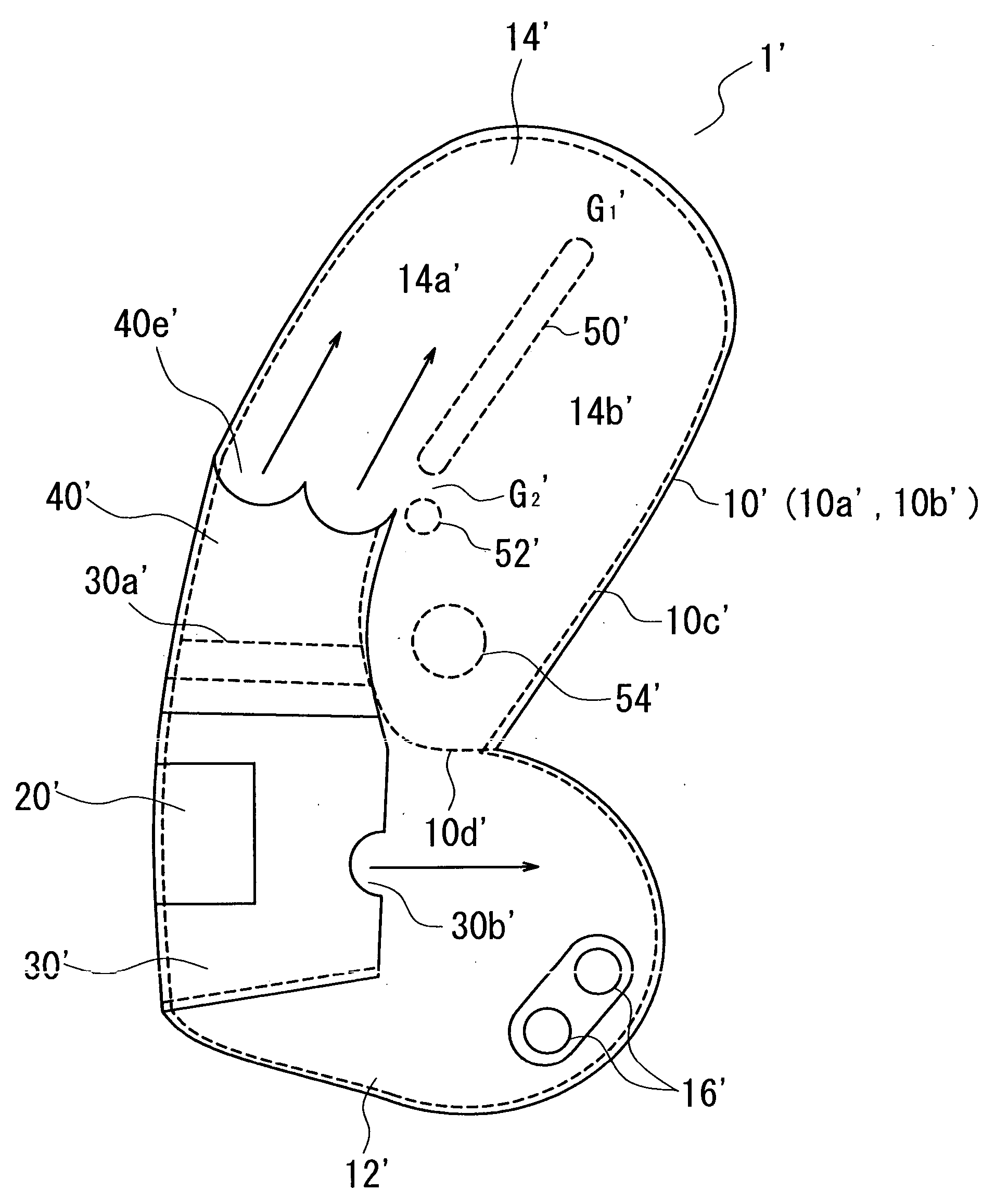
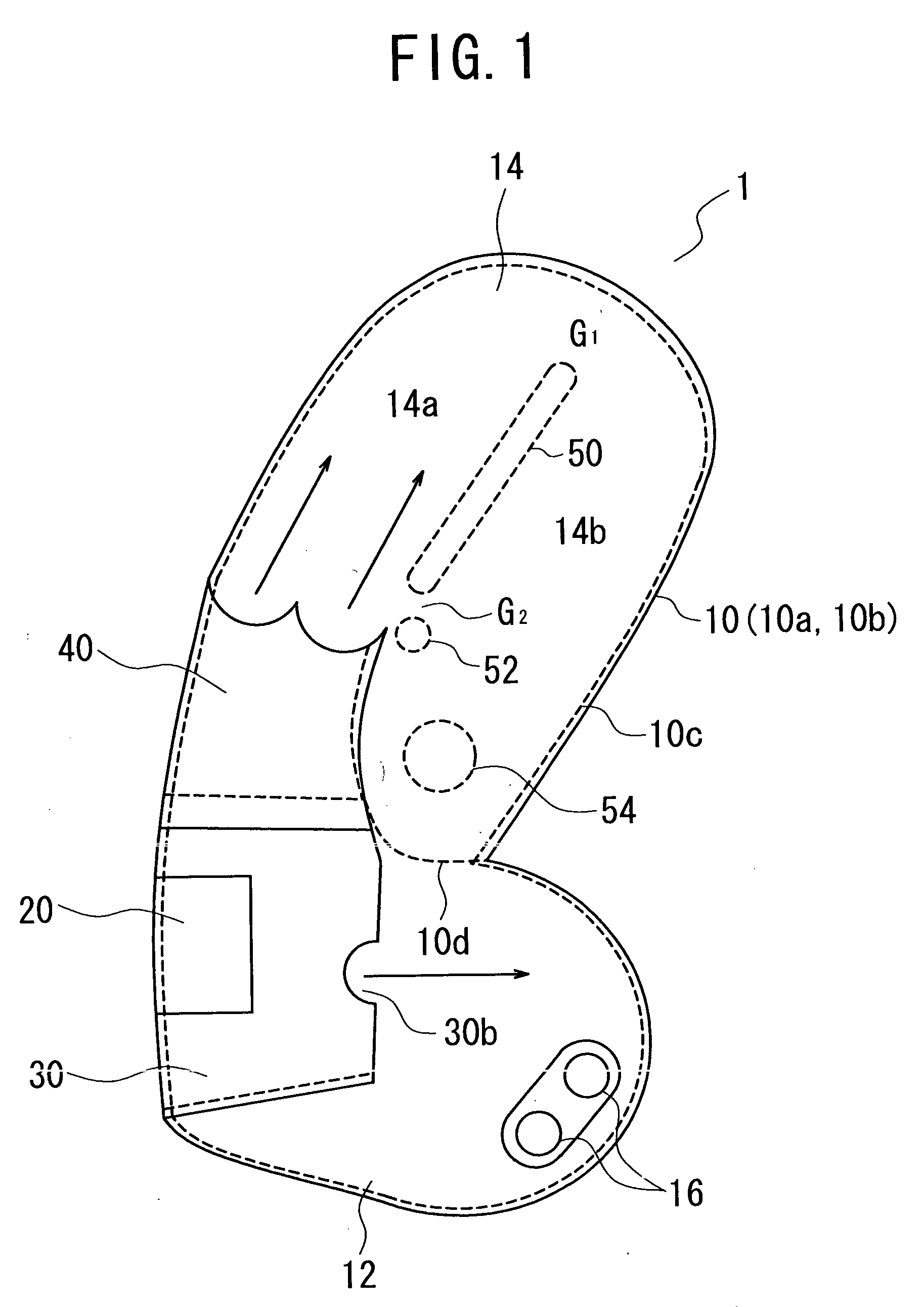
[0040]FIG. 1 is a schematic sectional view broadly showing the whole makeup of the air bag device against the side collision.

[0041] As shown in the figure, an air bag 10 of the air bag device 1 is formed by sewing together base clothes 10a, 10b, on the top face side, and rear face side of the air bag 10, respectively, at a seam 10c along the entire periphery thereof, each being made of, for example, a synthetic fabric such as polyamide, polyester, and so forth, with a resin coating applied thereto, for common use in air bags. Further, the air bag 10 is divided along another seam 10d branching off from the seam 10c, at which the base clothes 10a, 10b, on the front, and back sides of the air bag 10, respectively, are sewn together, into a lower air chamber 12 for protection of the chest (or the waist)...


PUM


Abstract

Expansion of an air bag can be smoothly effected even in a small space by controlling the air bag in thickness and introduction of the gas for expansion, and the protection of an occupant can be rapidly implemented with a relatively small volume of the gas. An air bag device comprises a first air chamber 12 for protection of the chest or the waist of an occupant, a second air chamber 14 for protection of the head of the occupant, and a lower portion of the diffuser bag 30 interposed therebetween for portioning out gas from an inflator 20, wherein the second air chamber 14 has a first tether 50 forming a gas passage 14a for guiding gas jetted from gas outlets of the lower portion of the diffuser bag 30 into the second air chamber 14 so as to go around the tether of a head protection region of an air bag 1, from the back side thereof toward the front side thereof, and has a second tether 52 for forming a gap provided at the lower end of the first tether 50 in the vicinity of the gas outlets, for letting a portion of the gas escape into a front part of the second air chamber 14.

Description

FIELD OF THE INVENTION [0001] The invention relates to an air bag device incorporating an air bag comprising a first air chamber provided with an inflator, for protection of the waist or the chest of an occupant, and a second air chamber into which gas of the inflator is guided from the first air chamber, for protection of the head of the occupant, and in particular, to an air bag device capable of being expanded in a limited space with ease, and guiding the gas to a head protection part of the second air chamber with ease. BACKGROUND OF THE INVENTION [0002] While use has been made of an air bag for protection of an occupant at the time of a side collision, it has been known that the waist of an occupant sitting down first comes into collision with a car's door to be then subjected to an impact, and the chest of the occupant subsequently comes into collision with the car's door. [0003] A conventional air bag device for use as a countermeasure against a side collision used to be stru...

Claims


Application Information

Patent Timeline
IPC IPC(8): B60R21/16B60R21/231B60R21/2346
CPCB60R21/23138B60R2021/23316B60R21/239B60R21/2346
Inventor TAGUCHI, SEIGOISHIGAME, KATSUYOSHISUGAHARA, TSUTOMUYAMAJI, NAOKIAZUMA, HIDETAKA
Owner MAZDA MOTOR CORP
Why Eureka
Try Eureka