System and method for monitoring tire pressure

a technology of system and method, applied in the field of system and method for monitoring tire pressure, can solve the problems of tire and rear tire overlap, burdensome and time-consuming method, tire and rear tire registration will be invalidated accordingly, etc., and achieve the effect of reducing tire pressur

Inactive Publication Date: 2006-01-05
HONDA MOTOR CO LTD
View PDF18 Cites 45 Cited by
  • Summary
  • Abstract
  • Description
  • Claims
  • Application Information

AI Technical Summary

Benefits of technology

[0016] Because the acceleration is used in the system described above, it is possible to promptly determine rolling or non-rolling of a tire if the vehicle starts traveling to reach a predetermined speed.
[0023] The predetermined speed is selected in such a manner that an acceleration induced by rotation of a wheel at the location of a sensor unit is sufficiently greater than an acceleration induced by vibration of a vehicle. In this way, the method enables the monitoring unit to register a sensor ID with the memory module without erroneously classifying a tire as a rolling or spare tire.
[0024] Furthermore, a driver is able to know simultaneously to which type of tire, a rolling or spare tire, the tire belongs, which has experienced a decrease in tire pressure.

Problems solved by technology

Because this type of registration uses the dedicated apparatus, it has been regarded as a burdensome and time consuming method.
Furthermore, when a driver replaces a worn tire with a spare tire or make a rotation of tires including a spare tire, the registration made at the maintenance shop will be invalid accordingly.
However, because a spare tire is stowed near rear tires, the radio waves transmitted by sensor units mounted on the spare tire and the rear tires tend to overlap, interfering with each other.
In addition, it may be that a radio wave transmitted by another vehicle traveling in parallel has an adverse effect on radio communication.
As a result, the monitoring unit is unable to properly recognize a reception level of radio wave received by each antenna, possibly leading to an erroneous registration of a sensor ID.
However, this method has the similar problem attributed to the fact that the spare tire is stowed near rear tires.
In this connection, the fact that a low frequency wave is typically used for the control signal is also contributes to the anomaly described above.
If the anomaly occurs, the monitoring unit simultaneously receives response signals from two sensor units, which results in a trouble that the monitoring unit can not distinguish the rear tire and the spare tire.
As a result, the monitoring unit is not able to make correct registration of a sensor ID.
The technical problems described above are all ascribed to the fact that a spare tire is stowed in a vehicle.
However, the method described above has a drawback that it takes long to know whether or not a tire is rolling based on the temperature increase.
Judging from this period of time it is concluded that the method is far from being applicable to a practical use.

Method used


Image

  • System and method for monitoring tire pressure
  • System and method for monitoring tire pressure
  • System and method for monitoring tire pressure

Examples


Embodiment Construction

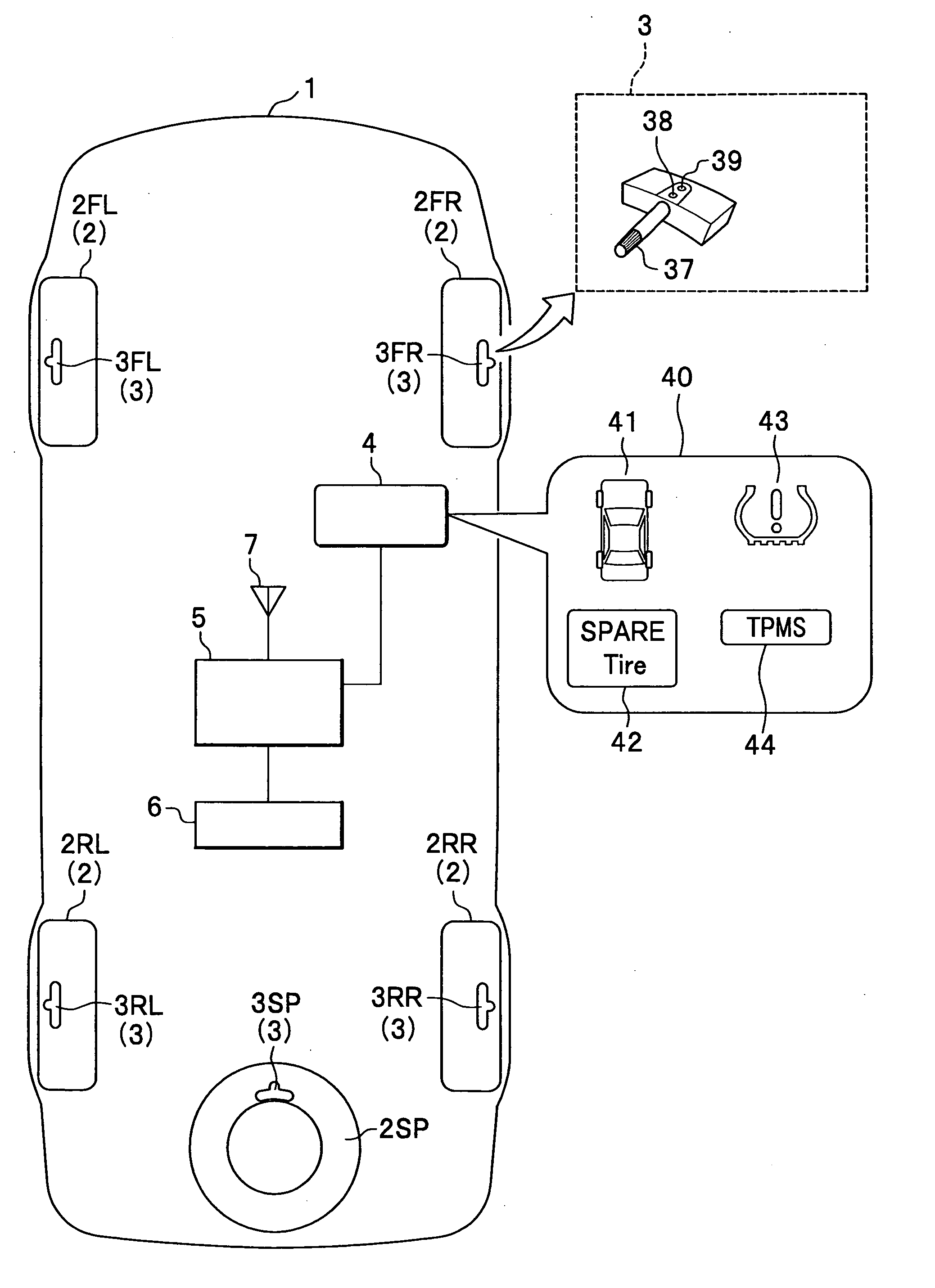
[0033] An embodiment of the present invention is now described with reference to the accompanying drawings.

[0034] As shown in FIG. 1, a vehicle 1, whose forward portion is shown at the top of FIG. 1, has four rolling wheels, namely a forward right wheel 2FR, a forward left wheel 2FL, a rear right wheel 2RR and a rear left wheel 2RL. In addition, the vehicle 1 has a spare wheel 2SP mounted on its rear portion. Sensor units 3FR, 3FL, 3RR, 3RL and 3SP are installed in tires attached to the wheels 2FR, 2FL, 2RR, 2RL and 2SP, respectively.

[0035] In description hereinafter, rolling wheels 2 is meant to represent all of the wheels 2FR, 2FL, 2RR and 2RL, so that they are distinguished from the spare wheel 2SP. In contrast, sensor units 3 is meant to represent all sensor units 3FR, 3FL, 3RR, 3RL and 3SP, not distinguishing the sensor unit 3SP installed in the tire attached to the spare wheel 2SP from other sensor units.

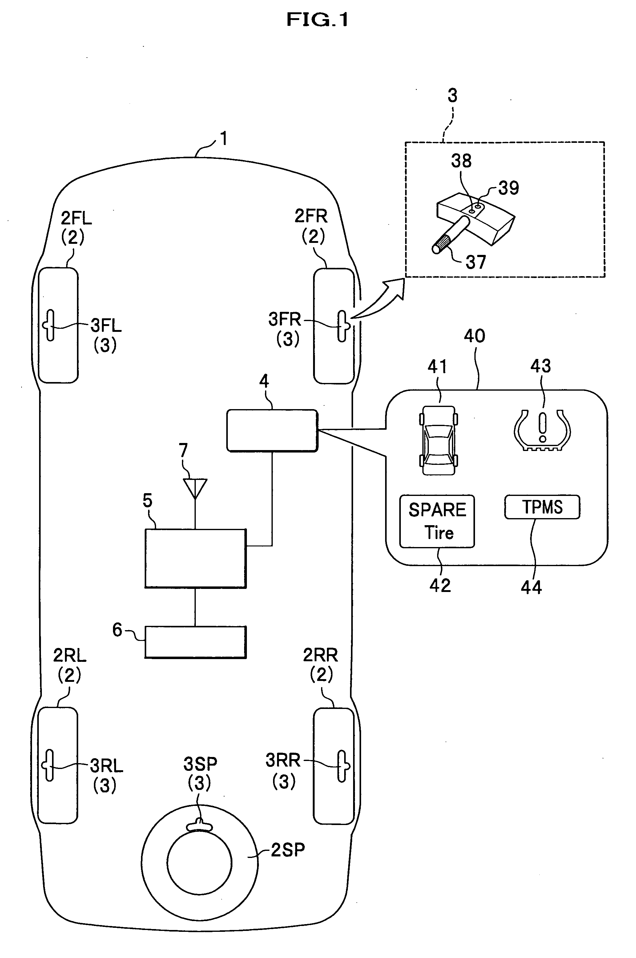
[0036] In the upper right portion of FIG. 1, a sensor unit 3 is schema...


PUM


Abstract

A system for monitoring a tire pressure includes a sensor unit and a monitoring unit. The sensor unit is mounted on a tire of a vehicle to detect an air pressure in the tire. The monitoring unit is mounted on the vehicle to monitor a signal indicative of the air pressure detected by the sensor unit so as to watch a decrease in the air pressure. The sensor unit includes an accelerometer so as to detect an acceleration acting on the tire. And the monitoring unit classifies the tire as one of a rolling tire and a spare tire based on a signal indicative of the acceleration transmitted by the sensor unit.

Description

BACKGROUND OF THE INVENTION [0001] The present invention relates to a system and method for monitoring a tire pressure. [0002] A tire pressure monitoring system (hereinafter referred to as “TPMS”), which timely calls a driver's attention to a decrease in a tire pressure of a traveling vehicle, has already been required for a new car as a compulsory system in North America. In addition, there is an indication that this system is becoming widespread in other regions. TPMS are categorized into a direct type (sensor type) which directly detects a tire pressure by an air pressure sensor, and an indirect type which estimates a decrease in a tire pressure based on a difference in a rotational speed of a tire. In the present specification, a TPMS is meant to represent a direct type of TPMS. [0003] Generally speaking, a TPMS includes sensor units, a monitoring unit and a display unit. Each sensor unit is installed in a tire attached to a wheel. The monitoring unit is mounted on a vehicle bod...

Claims


Application Information

Patent Timeline
Patent Type & Authority Applications(United States)
IPC IPC(8): B60C23/00
CPCB60C23/0416
Inventor BESSHO, MAKOTOKOMATSU, GORO
Owner HONDA MOTOR CO LTD
Why Eureka
Try Eureka