Annular or penannular prism

a technology of annular prisms and prisms, applied in the field of lenses and prisms, can solve problems such as light convergen

Inactive Publication Date: 2006-01-05
MARKOWITZ SAMUEL N
View PDF5 Cites 1 Cited by
  • Summary
  • Abstract
  • Description
  • Claims
  • Application Information

AI Technical Summary

Benefits of technology

[0006] An annular prism capable of causing light (or other radiation) to either converge or diverge is defined by an annulus of material which is transparent to the light (or other radiation). The annulus tapers radially towards either its outer periphery or its central aperture. If the annulus tapers towards its outer periphery, light converges. If the annulus tapers towards its central aperture, light diverges. The degree of tapering determines the de

Problems solved by technology

More particularly, lenses that are thicker at their cente

Method used


Image

  • Annular or penannular prism
  • Annular or penannular prism
  • Annular or penannular prism

Examples


Embodiment Construction

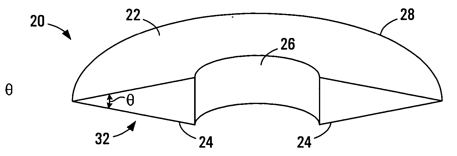
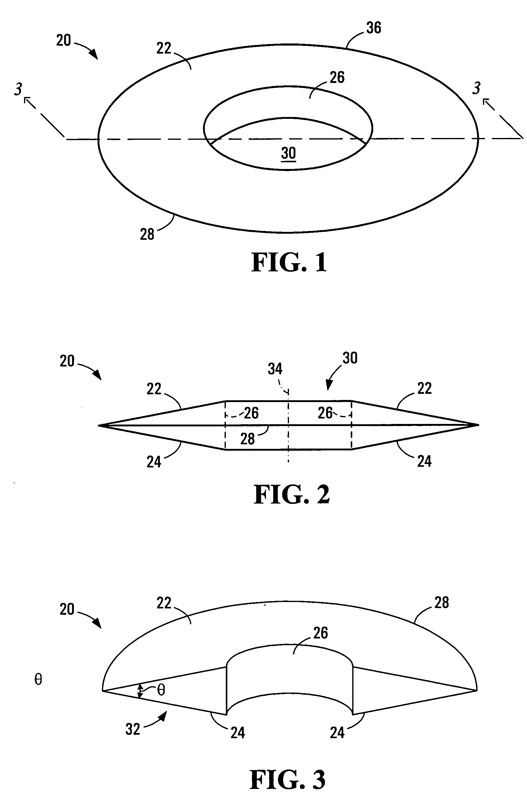
[0026] Referring to FIGS. 1-3, an annular prism 20 exemplary of a first embodiment of the present invention is illustrated in perspective view, in side elevation view, and in cross sectional perspective respectively. Annular prism 20 is capable of causing light travelling parallel to principal axis 34 (FIG. 2—described below) to converge. Prism 20 may thus be referred to as a “converging annular prism”.

[0027] As illustrated, annular prism 20 comprises an annulus 36 of transparent material, such as glass or plastic, having a central aperture 30. The annulus 36 has a front surface 22, a rear surface 24, and a cylindrical inner surface 26. As best seen in FIGS. 2 and 3, annulus 36 tapers towards its outer periphery, with the front and rear surfaces 22 and 24 ultimately converging to form the outer circumference 28 of the annulus 36.

[0028] As shown in FIG. 3, a cross section of the annular prism 20 formed by a plane that contains the principal axis 34 of the annulus 36 yields a pair o...


PUM


Abstract

An annular prism capable of causing light (or other radiation) to either converge or diverge is defined by an annulus of material which is transparent to the light (or other radiation). The annulus tapers radially towards either its outer periphery or its central aperture. If the annulus tapers towards its outer periphery, light converges. If the annulus tapers towards its central aperture, light diverges. The degree of tapering determines the degree of convergence or divergence. A cross section of the annulus formed by a plane containing a principal axis of the annulus viewed on only one side of the principal axis may have a triangular shape. In some embodiments, a segment of the annulus may be missing, resulting in a penannular prism which causes light (or other radiation) to converge or diverge about the principal axis of the incomplete annulus for some angular measure less than 360 degrees.

Description

FIELD OF THE INVENTION [0001] The present invention relates to lenses and prisms, and more particularly to lenses and prisms capable of converging or diverging light or other forms of radiation. BACKGROUND OF THE INVENTION [0002] In the field of optics, the use of lenses is commonplace. As is well known in the art, a lens is a piece of glass, plastic, or other transparent material with opposite surfaces, either or both of which are curved, by means of which light rays are refracted so that they converge or diverge to form an image. The shape of a lens determines whether the lens will cause light travelling parallel to the principal axis of the lens to converge or diverge. More particularly, lenses that are thicker at their center and thinner at their periphery cause light to converge. Such converging lenses are commonly used to correct hyperopia (farsightedness), an abnormal condition of the eye in which vision is better for distant objects than for near objects as a result of impro...

Claims


Application Information

Patent Timeline
IPC IPC(8): G02B25/00
CPCG02B5/001G02C7/14G02B5/04
Inventor MARKOWITZ, SAMUEL N.
Owner MARKOWITZ SAMUEL N
Why Eureka
Try Eureka