Tunable laser light source

a laser light source and tunable technology, applied in the direction of laser details, optical resonator shape and construction, semiconductor lasers, etc., can solve the problems of no tunable laser light source has been put into practice, distorted image or susceptibility to noise, and no optical beam deflector deflector deflector deflector deflector deflector deflector deflector deflector deflector deflector deflector deflector deflector deflector speed

Active Publication Date: 2006-08-29
SANTEC
View PDF12 Cites 158 Cited by
  • Summary
  • Abstract
  • Description
  • Claims
  • Application Information

AI Technical Summary

Benefits of technology

[0012]According to one aspect of the present invention having such features, the oscillation wavelength is changed by use of the tunable filter in the optical path of a resonator in laser oscillation. In the tunable filter an optical beam deflector deflects light and makes the light incident on the diffraction grating via the prism. The diffraction grating is used as a filter in which the wavelength changes in accordance with an incidence angle and reflects the light in the same direction as incidence light. Consequently, the tunable filter forms part of an optical path, thus permitting the oscillation wavelength to be determined by a wavelength selected. The laser light source changes the incidence angle on

Problems solved by technology

If the interval Δk is not an equal frequency interval, a problem, such as a distorted image or susceptibility to noise, arises.
However, no tunable laser light source has been put into practice which permits such high-spe

Method used


Image

  • Tunable laser light source
  • Tunable laser light source
  • Tunable laser light source

Examples


first embodiment

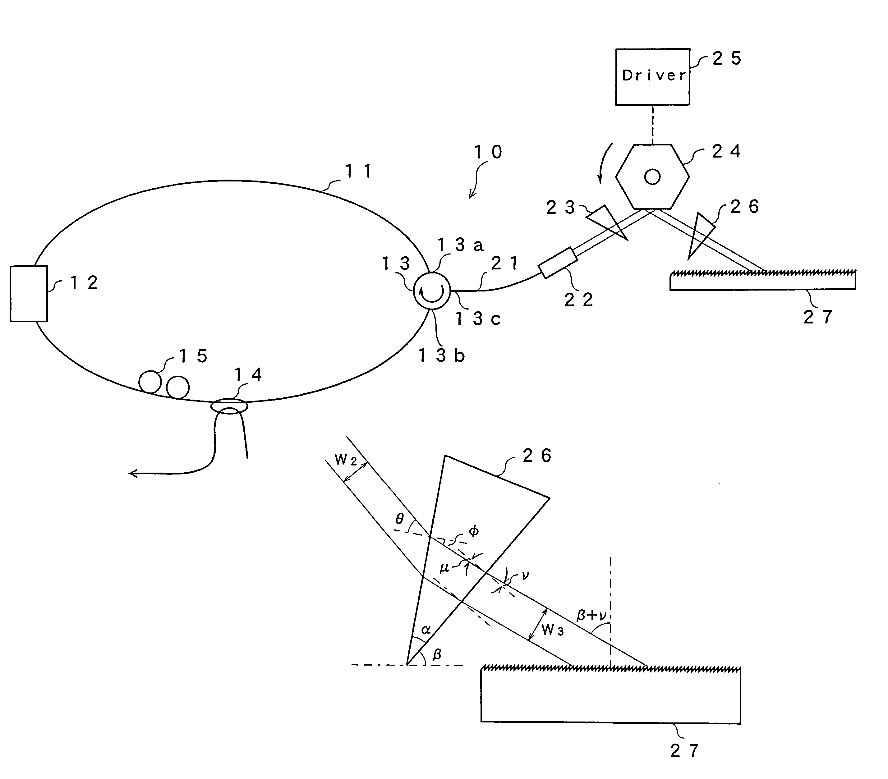
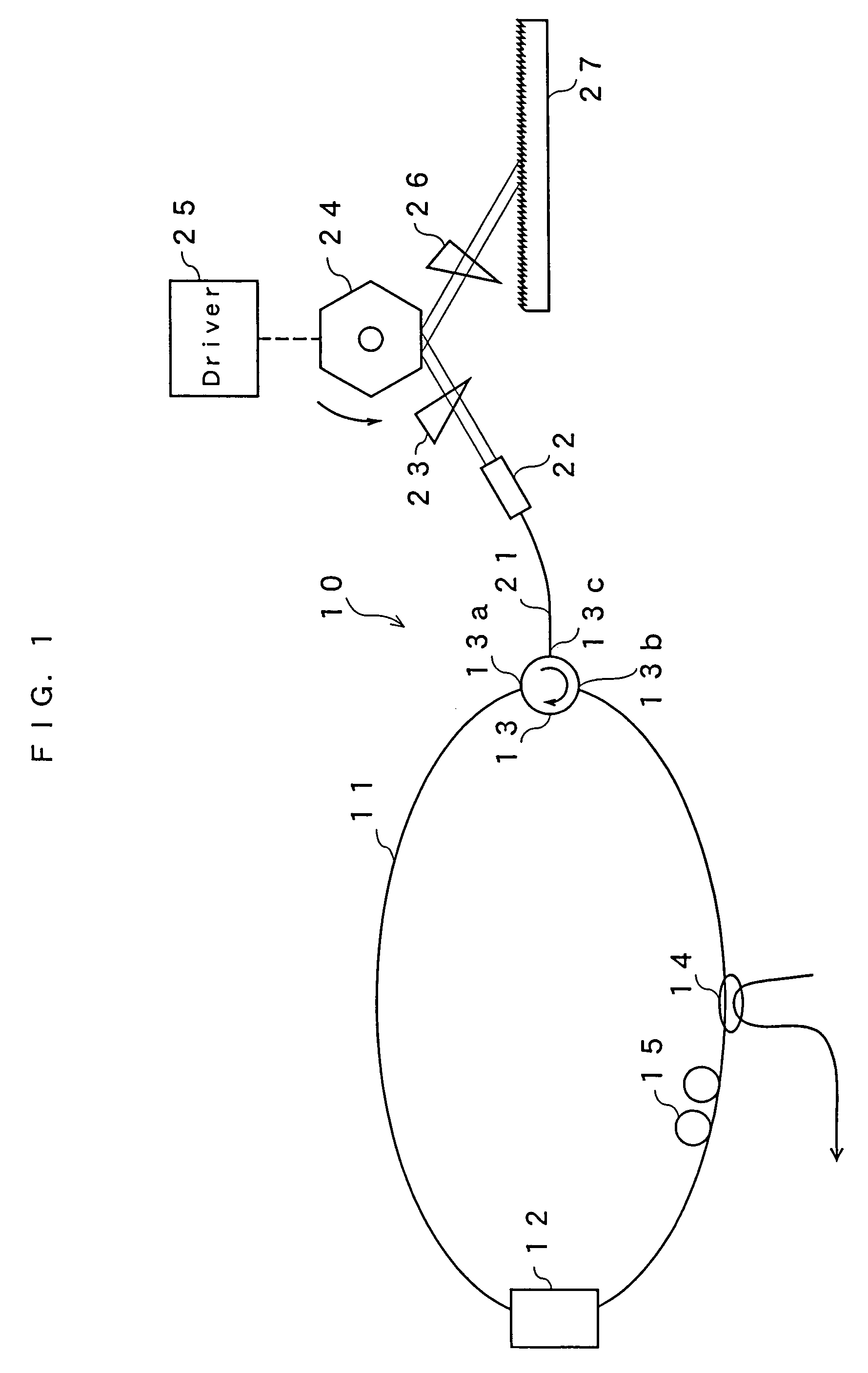
[0033]FIG. 1 is a schematic view showing the configuration of a tunable fiber laser light source according to a first embodiment of the present invention. A tunable fiber laser light source 10 of this embodiment forms a loop by including an optical fiber 11. In a part of the loop, a semiconductor optical amplifier as a gain medium 12, an optical circulator 13, an optical coupler 14 and a polarization controller 15 are provided. The optical circulator 13 regulates the direction of light passing through the optical fiber 11 to the arrow direction as shown in the figure. Specifically, input terminals 13a and 13b of the optical circulator 13 are connected to the optical fiber loop and incidence light from the input terminal 13a is emitted from a terminal 13c of the optical circulator 13. Incidence light from the terminal 13c of the optical circulator 13 is emitted from the terminal 13b. The incidence light from the terminal 13b is emitted from the terminal 13a. The optical coupler 14 ex...

second embodiment

[0059]FIG. 13 is a diagram showing a tunable fiber laser light source according to a second embodiment of the present invention. In the present embodiment, a polarization maintaining optical fiber 41 is used for an optical fiber loop to form laser oscillation path. Also in the present embodiment, a semiconductor optical amplifier as a gain medium 12, an optical circulator 13, and an optical coupler 14 are used. In the present embodiment, the polarization maintaining fiber 41 keeps the polarization plane of light oscillated while traveling around the loop constant in a predetermined direction, thereby, no polarization controller is required. Other structure of this embodiment is same as that of the first embodiment; thus, the same effect can be provided with relatively simple structure.

third embodiment

[0060]Next, a description will be given on a third embodiment of the present invention, referring to FIGS. 14 and 15. In the present embodiment, instead of providing an optical fiber in the form of a loop, a gain medium, an optical fiber, and a tunable filter part are used to form an optical resonator. As a gain medium 51, a semiconductor optical amplifier (SOA), a Fabry-Perot laser diode (FPLD), a Super Luminescent Diode (SLD), or the like is used. As shown in FIG. 15, the gain medium 51 has one surface 51a provided as a high reflection film having a reflectance of, for example, approximately 80 to 100% and has the other surface 51b provided as a non-reflection film. Light transmitted through the surface 51b is connected to an optical fiber 53 via a collimate lens 52. The optical fiber 53 is connected to a polarization controller 54 with the other end thereof provided with the aforementioned tunable filter 56 of the first embodiment. The tunable filter 56 is, as is the case with th...


PUM


Abstract

A gain medium 12 and a tunable filter are provided in an optical path of laser oscillation. The tunable filter has an optical beam deflector for periodically changing an optical beam at a constant angular speed, a prism 26 on which deflected light is made incident, and a diffraction grating 27. Appropriate selection of the apex angle α of the prism 26 and an angle β formed by the prism 26 and the diffraction grating 27 can provide a tunable laser light source for changing the oscillation frequency at high speed and a constant variation rate.

Description

BACKGROUND OF THE INVENTION[0001]1. Field of the Invention[0002]The present invention relates to a tunable laser light source, which generates monochromatic light to scan continuously in a wavelength range at a constant variation rate thereof.[0003]2. Discussion of the Related Art[0004]Hitherto, as a light source of an analyzer for analyzing an object to be measured by irradiating the object with light, a light source of a wide bandwidth is used. In spectral analysis, there is widely used a method of projecting light of a wide bandwidth to an object to be measured, spatially decomposing reflection light or transmission light of the projected light to wavelength components by a grating or the like, Fourier-analyzing the frequency components by an interferometer, and making an analysis. As a light source used in such a method, for example, a white light source, an ASE light source using an erbium doped fiber (EDF), or the like is used. In such spectral analysis, however, the intensity...

Claims


Application Information

Patent Timeline
IPC IPC(8): H01S3/10H01S3/08
CPCH01S5/141H01S3/067H01S3/06791H01S3/08013H01S5/146H01S3/1055H01S3/105
Inventor CHONG, CHANGHO
Owner SANTEC
Why Eureka
Try Eureka