Amplifier circuit and amplifying method

a technology of amplifier circuit and amplifier circuit, applied in the direction of amplifier modification to reduce non-linear distortion, digital transmission, baseband system details, etc., can solve the problems of difficult to predict factors, errors may become distortion components of signals, etc., to suppress the circuit scale of amplifier circuit, low distortion, and high power efficiency

Inactive Publication Date: 2007-04-05
PANASONIC CORP
View PDF24 Cites 48 Cited by
  • Summary
  • Abstract
  • Description
  • Claims
  • Application Information

AI Technical Summary

Benefits of technology

[0013] According to the present invention, it is possible to suppress the circuit scale of an amplifier circuit and obtain an output signal with high power efficiency and little distortion.

Problems solved by technology

However, in the event that errors occur in the gain or phase of the amplifiers in the two systems, vectors of signals after amplification and combining may differ from vectors of an intended output signal, i.e., these errors may become distortion components of signals.
Further, at the amplifier circuit 10a, not only is it difficult to predict factors for these errors, but characteristics fluctuate due to an environment such as temperature or the like.

Method used


Image

  • Amplifier circuit and amplifying method
  • Amplifier circuit and amplifying method
  • Amplifier circuit and amplifying method

Examples


first embodiment

[0032] (First Embodiment)

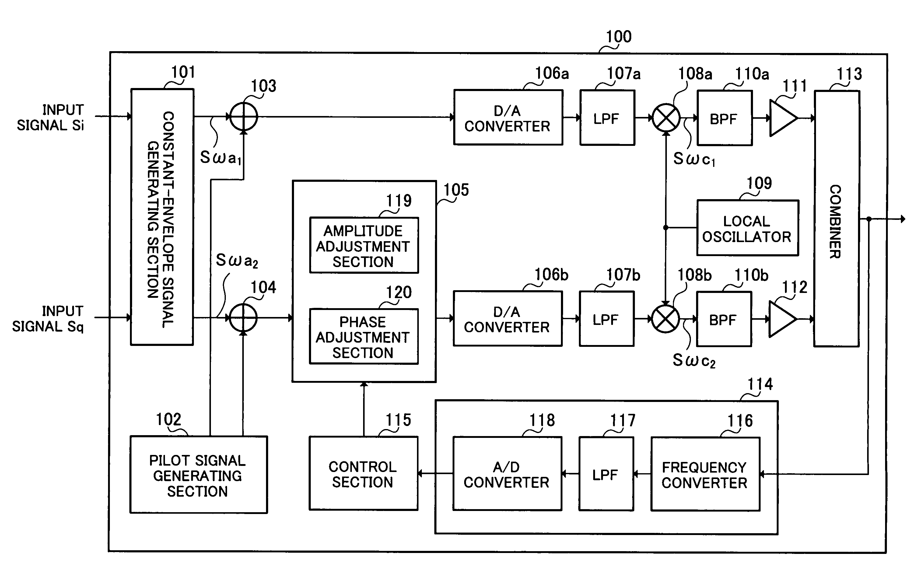
[0033]FIG. 4 is a block diagram showing a configuration for an amplifier circuit of a first embodiment of the present invention.

[0034] Amplifier circuit 100 shown in FIG. 4 comprises constant-envelope signal generating section 101, pilot signal generating section 102, first addition section 103, second addition section 104, vector adjustment section 105, two D / A converters 106a and 106b, two low-pass filters (LPF) 107a and 107b, two mixers 108a and 108b, local oscillator 109, two band pass filters (BPF) 110a and 10b, first amplifier 111, second amplifier 112, combiner 113, pilot signal detector 114, and control section 115.

[0035] Further, pilot signal detector 114 comprises frequency converter 116, LPF 117, and A / D converter 118. Moreover, vector adjustment section 105 comprises amplitude adjustment section 119 and phase adjustment section 120.

[0036] Constant-envelope signal generating section 101 generates two constant-envelope signals, i.e. a first cons...

second embodiment

[0081] (Second Embodiment)

[0082]FIG. 7 is a block diagram showing a configuration for an amplifier circuit of a second embodiment of the present invention. The amplifier circuit of this embodiment has a basic configuration similar to amplifier circuit 100 described in the first embodiment, the same reference numerals are assigned to the same structural elements, and detailed description thereof is therefore omitted.

[0083] Amplifier circuit 200 shown in FIG. 7 has pilot signal generating section 201 in place of pilot signal generating section 102 of amplifier circuit 100 shown in FIG. 4.

[0084] A feature of this embodiment is that two pilot signals are generated in such a manner that pilot signal components cancel each other out after combined in the event that any differences in gain and phase are not generated from respective signals being outputted from first addition section 103 and second addition section 104 until the signals are combined by the combiner 113.

[0085] In the fol...

third embodiment

[0101] (Third Embodiment)

[0102]FIG. 10 is a block diagram showing a configuration for an amplifier circuit of a third embodiment of the present invention. The amplifier circuit of this embodiment has a basic configuration similar to amplifier circuit 100 described in the first embodiment, the same reference numerals are assigned to the same structural elements, and detailed description thereof is therefore omitted.

[0103] Amplifier circuit 300 shown in FIG. 10 adds frequency characteristic correction section 301 to the configuration of amplifier circuit 100 shown in FIG. 4, and adopts a configuration provided with pilot signal detection section 302, control section 303 and pilot signal generating section 304 in place of pilot signal detector 114, control section 115 and pilot signal generating section 102. Further, pilot signal detection section 302 also adopts a configuration where frequency converter 305, LPF 306 and A / D converter 307 are added to the configuration of pilot signal...


PUM


Abstract

An amplifier circuit capable of suppressing the circuit scale thereof and obtaining an output signal with high power efficiency and little distortion is disclosed. In this circuit, constant-envelope signal generating section (101) generates a plurality of constant-envelope signals from an input signal. Pilot signal generating section (102) generates a plurality of pilot signals associated with the generated plurality of constant envelope signals, the plurality of pilot signals having predetermined amplitudes, predetermined phases and predetermined frequencies, respectively, the phases and frequencies being different from each other. First addition section (103) and second addition section (104) add the plurality of pilot signals to the generated plurality of constant-envelope signals. First amplifier (111) and second amplifier (112) amplify the plurality of constant-envelope signals to which the plurality of pilot signals are added. Vector adjustment section (105) corrects the amplitude or phase of one of the generated plurality of constant-envelope signals using a signal component included in the amplified plurality of constant-envelope signals and corresponding to the plurality of pilot signals.

Description

TECHNICAL FIELD [0001] The present invention relates to an amplifier circuit and amplifying method, and particularly relates to an amplifier circuit and amplifying method amplifying a transmission signal at transmission apparatus employed in wireless communication and broadcasting. BACKGROUND ART [0002] In recent years, it becomes more often that digitally modulated signals are transmitted at transmission apparatuses employed in wireless communication and broadcasting. These signals are now able to carry information in an amplitude direction due to introduction of M-ary techniques, and linearity is therefore required in an amplifier circuit employed in a transmission apparatus. On the other hand, high power efficiency is required to an amplifier circuit in order to curtail the power consumption of an apparatus. Various techniques have been proposed for distortion correction and efficiency improvement, in order to pursue both of the linearity and power efficiency of the amplifier cir...

Claims


Application Information

Patent Timeline
Patent Type & Authority Applications(United States)
IPC IPC(8): H04L25/49H03F3/66H03F1/02H03F1/32
CPCH03F1/0294H03F2200/372
Inventor IKEDA, KAZUHIKOIZUMI, TAKASHI
Owner PANASONIC CORP
Why Eureka
Try Eureka