Anti-unmanned aerial vehicle detection system and control method thereof

A detection system and anti-drone technology, applied to radio wave measurement systems, measurement devices, computer components, etc., can solve the problems of reducing the efficiency and effect of drone reconnaissance, and reach triggers and I/O pins Rich, highly customizable, low-power effects

Active Publication Date: 2016-11-23
TELECAST TECH CORP
View PDF4 Cites 47 Cited by
  • Summary
  • Abstract
  • Description
  • Claims
  • Application Information

AI Technical Summary

Problems solved by technology

First of all, it is necessary to detect, track and warn the UAV, and then according to the actual situation, choose the hard damage to the UAV or the soft damage to interfere with it; in addition, it is also necessary to take a proactive camouflage protection Methods and means to reduce the reconnaissance efficiency and effect of the opponent's drone

Method used


Image

  • Anti-unmanned aerial vehicle detection system and control method thereof
  • Anti-unmanned aerial vehicle detection system and control method thereof
  • Anti-unmanned aerial vehicle detection system and control method thereof

Examples


Embodiment 1

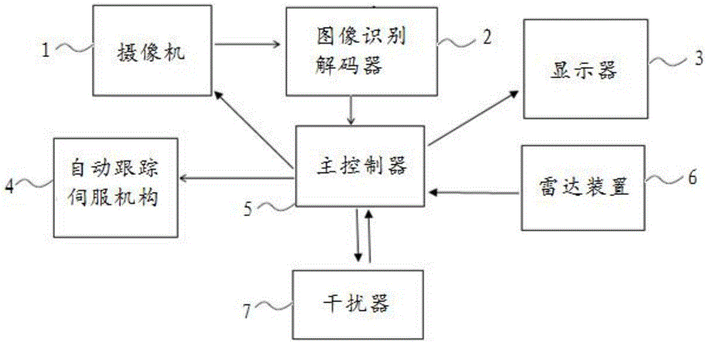
[0047] Such as figure 1 As shown, the anti-drone detection system includes a camera 1 with an optical lens, a display 3, an automatic tracking servo mechanism 4 for controlling the movement of the camera, a radar device 6, a main controller 5, a jammer 7 and a picture of a drone stored therein. Image recognition decoder 2 for information; the signal output end of the camera 1 is connected to the signal input end of the image recognition decoder 2, and the signal output end of the image recognition decoder 2 is connected to the first of the main controller 5 signal input end, the signal output end of the radar device 6 is connected to the second signal input end of the main controller 5, and the first signal output end of the main controller 5 is connected to the signal input end of the camera 1, so The second signal output end of the main controller 5 is connected to the signal input end of the display 3, the third signal output end of the main controller 5 is connected to the...

Embodiment 2

[0049] This embodiment is on the basis of embodiment 1:

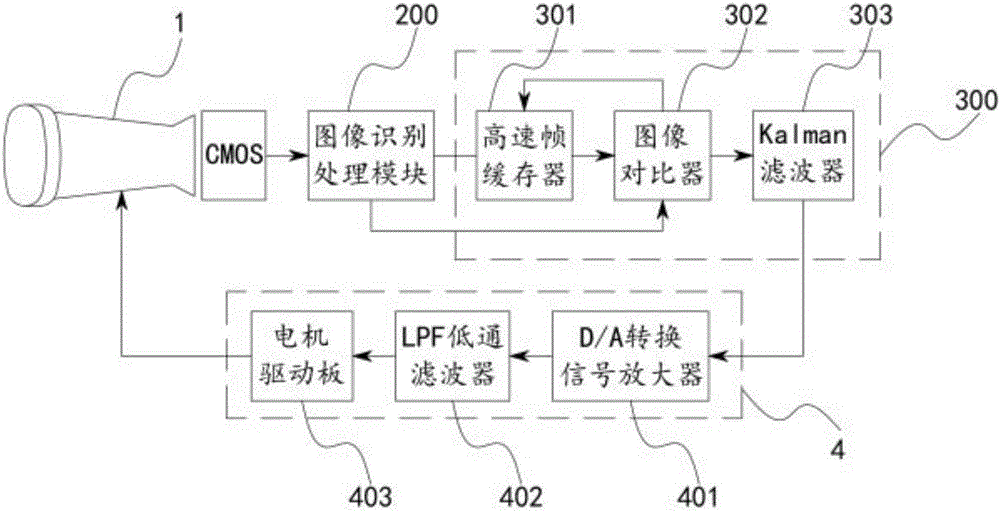
[0050] Such as image 3 As shown, the image recognition decoder 2 includes an image recognition processing module 200 and an image analysis module 300, the signal output end of the image recognition processing module 200 is connected to the signal input end of the image analysis module 300; the image analysis module 300 includes a high-speed frame buffer 301, an image comparator 302 and a Kalman filter 303, the first signal input end of the image comparator 302 is connected to the signal output end of the image recognition processing module 200, and the high-speed frame buffer 301 The signal output end of the image comparator 302 is connected to the second signal input end of the image comparator 302, the signal input end of the high-speed frame buffer 301 is connected to the first signal output end of the image comparator 302, and the image comparator 302 The second signal output end is connected to the signal input e...

Embodiment 3

[0052] This embodiment is on the basis of embodiment 2:

[0053] The Kalman filter 303 has a built-in FPGA chip for implementing the Kalman algorithm.

[0054] Such as image 3 and Figure 4 As shown, the automatic tracking servo mechanism 4 of the present invention includes a horizontal drive motor that drives the camera to move in the horizontal direction, a vertical drive motor that drives the camera to move in the vertical direction, a motor drive board 403, an LPF low-pass filter 402 and a D / A conversion signal amplifier 401, the signal input end of the D / A conversion signal amplifier 401 is connected to the signal output end of the Kalman filter 303, and the signal output end of the D / A conversion signal amplifier 401 is connected to the LPF low pass The signal input end of the filter 402, the signal output end of the LPF low-pass filter 402 is connected to the signal input end of the motor drive board 403, and the first signal output end of the motor drive board 403 ...


PUM


Abstract

The invention provides an anti-unmanned aerial vehicle detection system and a control method thereof. The system comprises a camera provided with an optical lens, a displayer, an automatic tracking servo mechanism controlling the camera to move, a radar device, a main controller, an interference unit, and an image identification decoder storing unmanned aerial vehicle image information. By the adoption of a photoelectric surveillance radar device combining the radar device with an optical tracking system, radar detection, optical image identification and electromagnetic interference are integrated, and the system and method play an important role in improving organic integration of unmanned aerial vehicle monitoring, the optical system and the radar device.

Description

technical field [0001] The invention belongs to the technical field of anti-drone, and in particular relates to an anti-drone detection system and a control method thereof. Background technique [0002] With the emergence of new drones, accidents related to drones are constantly coming into people's field of vision, and it is no longer uncommon to use drones for criminal activities. Uncontrolled drones fall on pedestrians or objects; amateur drone operators fly drones into no-fly zones; drones interfere with civil aviation and firefighting operations; drug traffickers in Mexico and Latin America are using homemade drones Human-machine drug trafficking, British criminal groups use drones to smuggle drugs, mobile phones and money to prisoners. As a result, the anti-drone system also came into being during the booming development of the drone industry. [0003] The anti-drone technology system consists of detection, tracking and early warning technology, damage technology, ja...

Claims


Application Information

Patent Timeline
Patent Type & Authority Applications(China)
IPC IPC(8): G01S13/86H04K3/00G06K9/00
CPCH04K3/62H04K3/825G01S13/867G06V20/52
Inventor 蔡茂杨钦
Owner TELECAST TECH CORP
Why Eureka
Try Eureka