Vehicular lamp

a technology for lamps and tail lamps, applied in the field of vehicle lamps, can solve the problems of reducing the visibility of lit tail lamps, affecting the appearance of lamps, so as to achieve the effect of free of deterioration of external appearance and increased visibility

Inactive Publication Date: 2006-01-05
KOITO MFG CO LTD
View PDF1 Cites 26 Cited by
  • Summary
  • Abstract
  • Description
  • Claims
  • Application Information

AI Technical Summary

Benefits of technology

[0009] Accordingly, the object of the present invention is to provide a vehicular lamp that is free of deterioration of the external appearance caused by the darkly visible partition that defines a lamp chamber and further has an increased visibility.
[0013] According to the present invention, the inner lens that covers the partition is brought into a lit state by the light that is from the light source and guided to radiate from the surface of the inner lens. As a result, the partition does not appear dark and the lamp becomes brightly lit, thus improving the visibility of the lamp with an increased styling effect.
[0014] Furthermore, in the present invention, since a part of the light from the light source passes through the window portion of the partition to radiate to the adjacent region and is subsequently reflected so that the lamp becomes luminescent, the brightness of the lamp increases further, and its visibility improves even further. The different lit states in a plurality of regions inside the lamp body are blended together to form a lamp that has a novel exterior appearance.

Problems solved by technology

Consequently, when only the tail lamp is lit, the light-shielding partitions tend to become visible darkly.
This lowers the visibility of the lit tail lamp and causes a problem in regards to the lamp's exterior appearance from the standpoint of styling.
In particular, since the side surface of the circular rib appears wide when the lamp is viewed from the side, the area of the darkly visible region becomes larger, lowering the visibility of the lamp.
For this reason, if the inner lens of the Japanese Patent Laid-Open Publication No. 2000-231806 was applied to a rear combination lamp as described above in order to demarcate the stop lamp within the tail lamp, the darkly visible area caused by the circular rib of the inner lens would become extremely large when the tail lamp is lit, and this lowers the visibility of the tail lamp and causes problems from the lamp styling standpoint.

Method used


Image

  • Vehicular lamp
  • Vehicular lamp
  • Vehicular lamp

Examples


Embodiment Construction

[0020] The present invention will now be described with reference to the accompanying drawings.

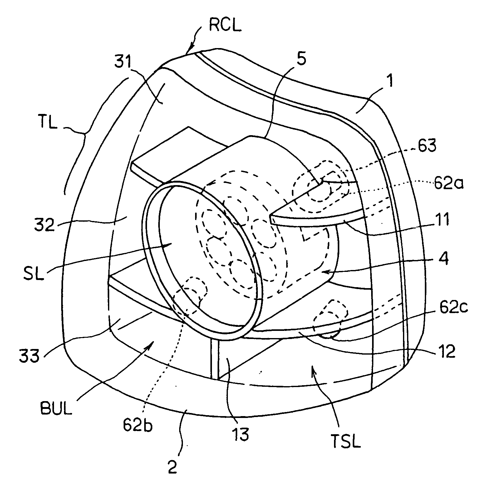
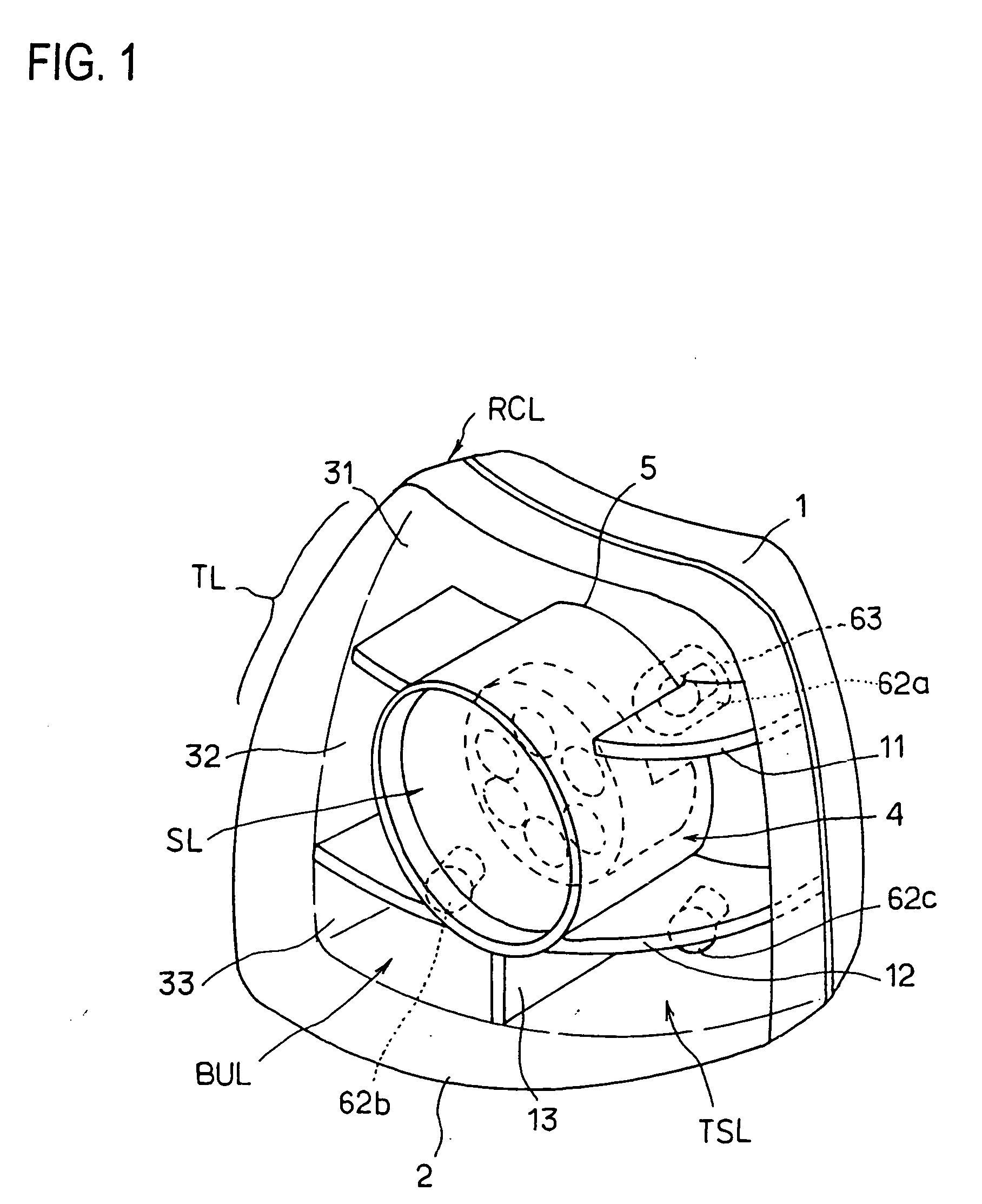
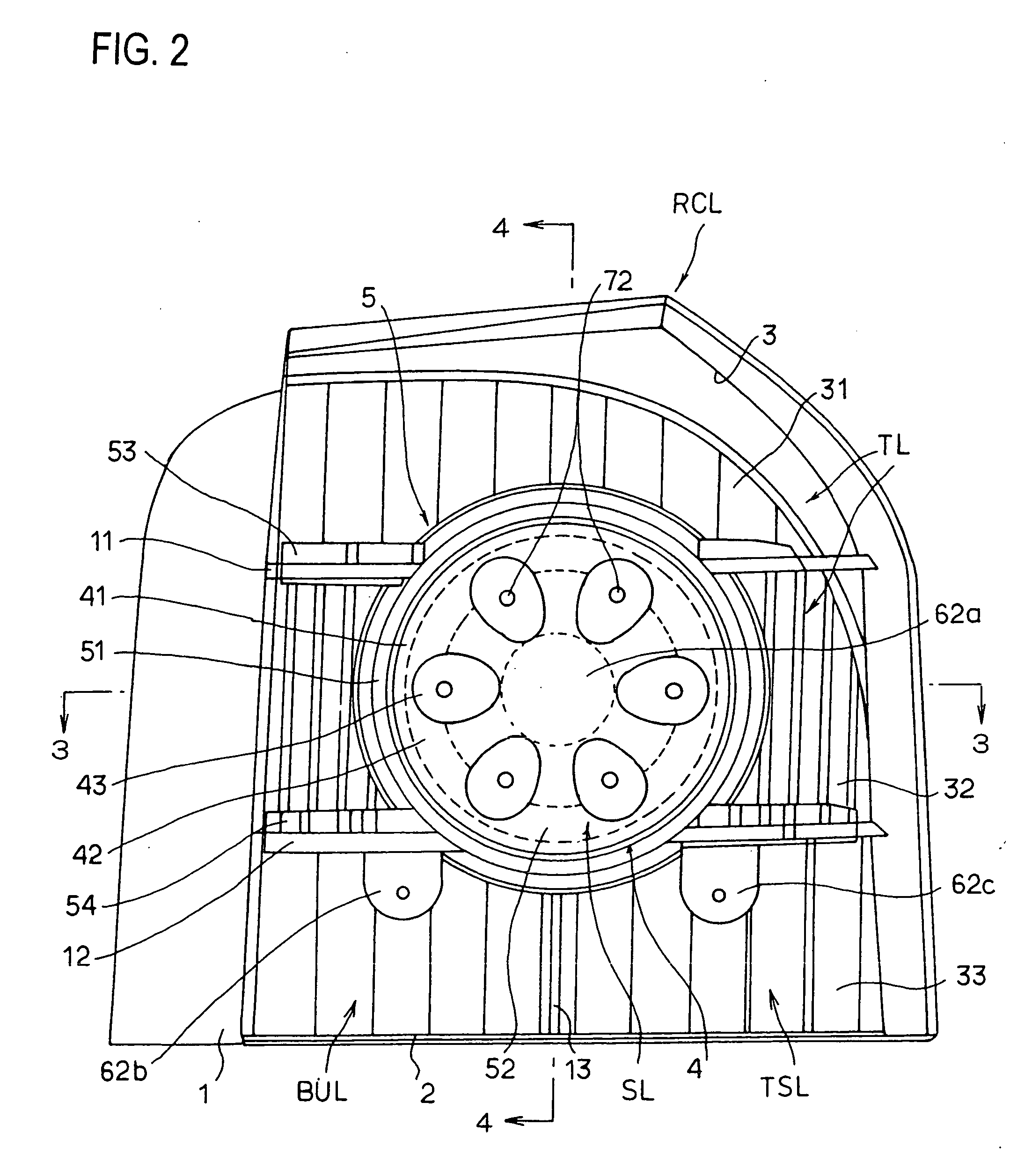
[0021] The rear combination lamp RCL is mounted on the right-hand rear portion of a vehicle, and it has a lamp chamber 3 configured inside the rear combination lamp RCL using a lamp body 1 and an outer lens 2 which is attached to the front opening of the lamp body 1. In the lamp body 1, a pair of upper and lower lateral partitions 11 and 12 are formed so that these partitions demarcate a high-level region 31, an intermediate-level region 32, and a lower-level region 33, each extending in the lateral direction (horizontal direction) within the lamp chamber 3 as seen from FIG. 2. In addition, a vertical partition (perpendicular partition) 13 is formed in the lower-level region 33 at the center with reference to the right-left direction, thus forming lower right and lower left regions in the lower-level region 33. A turn signal lamp TSL and a backup lamp BUL are respectively formed in the lo...


PUM


Abstract

A vehicular lamp including partitions 11 and 12, 13 that demarcate the interior of a lamp chamber 3 defined by a lamp body 1 and an outer lens 2 into a plurality of regions 31 to 33, a light source 62a disposed in at least one of the regions, an inner lens 5 provided to cover the partitions, a means for guiding a part of the light emitted from the light source 62a into the inner lens 5. In addition to one region demarcated by the partitions is brought into a lit state by light directly emitted from the light source 62a, the inner lens 5 is lit by the light from the light source 62a that is guided into and radiates from the inner lens surface.

Description

BACKGROUND OF THE INVENTION [0001] 1. Technical Field [0002] The present invention relates to a vehicular lamp having improved appearance or visibility and a novel external appearance. [0003] 2. Description of the Related Art [0004] Vehicular lamps used as marker lamps are installed in the rear portion of a vehicle and often configured as so-called combination lamps. In such a combination lamp, a plurality of lamps having different functions are installed inside a single lamp body. In particular, a typical combination lamp is a tail lamp, and it includes a stop lamp that lights when the driver steps on the brake, a backup lamp that lights when the vehicle backs up, and a turn signal lamp that is lighted when the vehicle changes the direction. [0005] Typically, in a rear combination lamp, a plurality of lamp chambers are demarcated and formed by partitions provided inside a single lamp body, and function lamps are configured within each lamp chamber. In a rear combination lamp with s...

Claims


Application Information

Patent Timeline
Patent Type & Authority Applications(United States)
IPC IPC(8): F21V1/00F21Y101/00
CPCB60Q1/0052B60Q1/0058F21S48/24F21S48/215B60Q1/2607F21S43/14F21S43/40
Inventor KOIZUMI, HIROYATEZUKA, NOBUTAKATAKEDA, HAJIMESUZUKI, HIDENORI
Owner KOITO MFG CO LTD
Why Eureka
Try Eureka