Apparatus for image forming capable of applying a high fixing-nip pressure easily releasable when a recording sheet is stuck in a fixing mechanism

a technology of fixing mechanism and apparatus, which is applied in the field of apparatus for image forming, can solve the problems of difficult to remove recording materials, difficult to release the pressure between the heat roller and the pressure roller, and the fixing performance tends to be degraded, and achieves the effect of high fixing-nip pressure easy releasabl

Active Publication Date: 2006-01-05
RICOH KK
View PDF6 Cites 60 Cited by
  • Summary
  • Abstract
  • Description
  • Claims
  • Application Information

AI Technical Summary

Benefits of technology

[0012] This patent specification describes a novel image forming apparatus capable of applying a high fixing-nip pressure easily releasable when a recording sheet is stuck in a fixing mechanism. As one example, a novel image forming system includes an image forming mechanism and a fixing mechanism. The fixing mechanism includes first and second fixing members configured to face each other to hold recording materials, a lock member configured to have first and second end portions and a locking portion located between the first and the second end portions, a pressuring lever configured to have one end pivotably held, a pressure release lever having a first portion at one end turnably holding the lock member and a second portion turnably holding the pressuring lever at another end of the pressuring lever and configured to turn between a lock position and a release position so that the first portion is located between the second portion and the locking portion of the lock member when the pressure release lever is at the release position and the second portion is located at the locking portion of the lock member when the pressure release lever is at the lock position and an elastic member configured to pull the lock member capturing the second portion of the pressure release lever in a direction from the first fixing member to the second fixing member at the lock position.

Problems solved by technology

The recording material is, however, tightly held at the pressure nip by the pair of rollers and therefore it is not easy to remove the recording material.
Therefore, by these two phenomena, the fixing performance tends to be degraded.
If the pressing force is so increased, however, it becomes difficult to release the pressure between the heat roller and the pressure roller with the pressure releasing mechanism such as the pressure release lever.

Method used


Image

  • Apparatus for image forming capable of applying a high fixing-nip pressure easily releasable when a recording sheet is stuck in a fixing mechanism
  • Apparatus for image forming capable of applying a high fixing-nip pressure easily releasable when a recording sheet is stuck in a fixing mechanism
  • Apparatus for image forming capable of applying a high fixing-nip pressure easily releasable when a recording sheet is stuck in a fixing mechanism

Examples


Embodiment Construction

[0021] In describing preferred embodiments illustrated in the drawings, specific terminology is employed for the sake of clarity. However, the disclosure of this patent specification is not intended to be limited to the specific terminology so selected and it is to be understood that each specific element includes all technical equivalents that operate in a similar manner. For example, a printer installed in an image forming system is disclosed in this specification. However the disclosure of this patent is applicable to other similar equipment such as copiers and facsimiles.

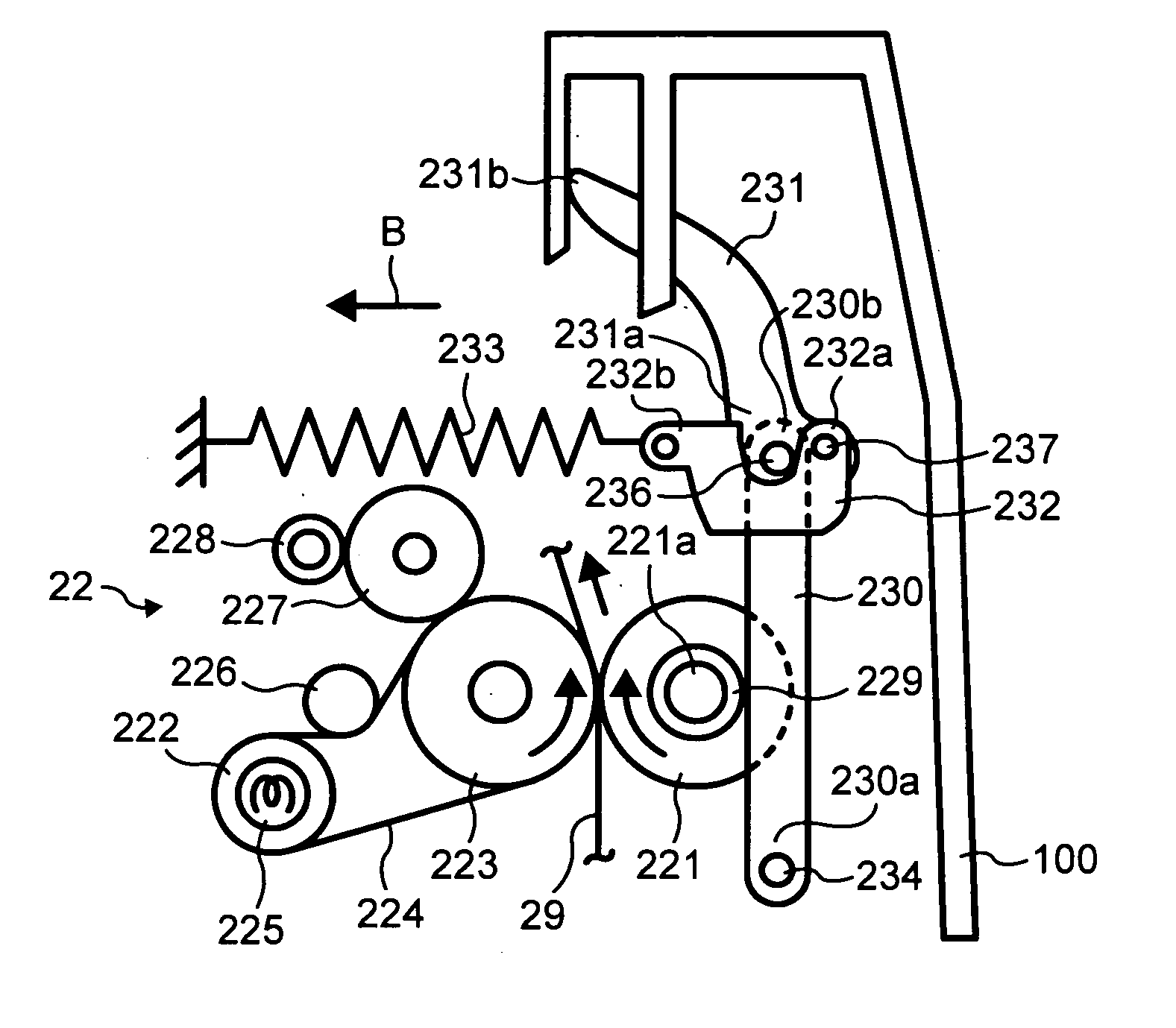
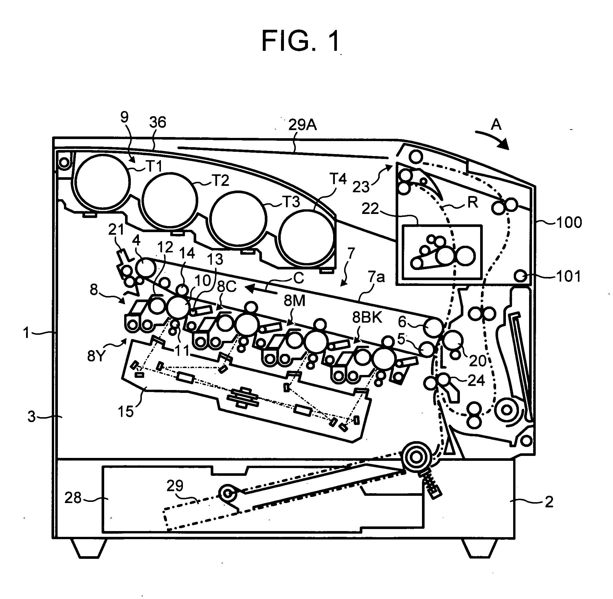
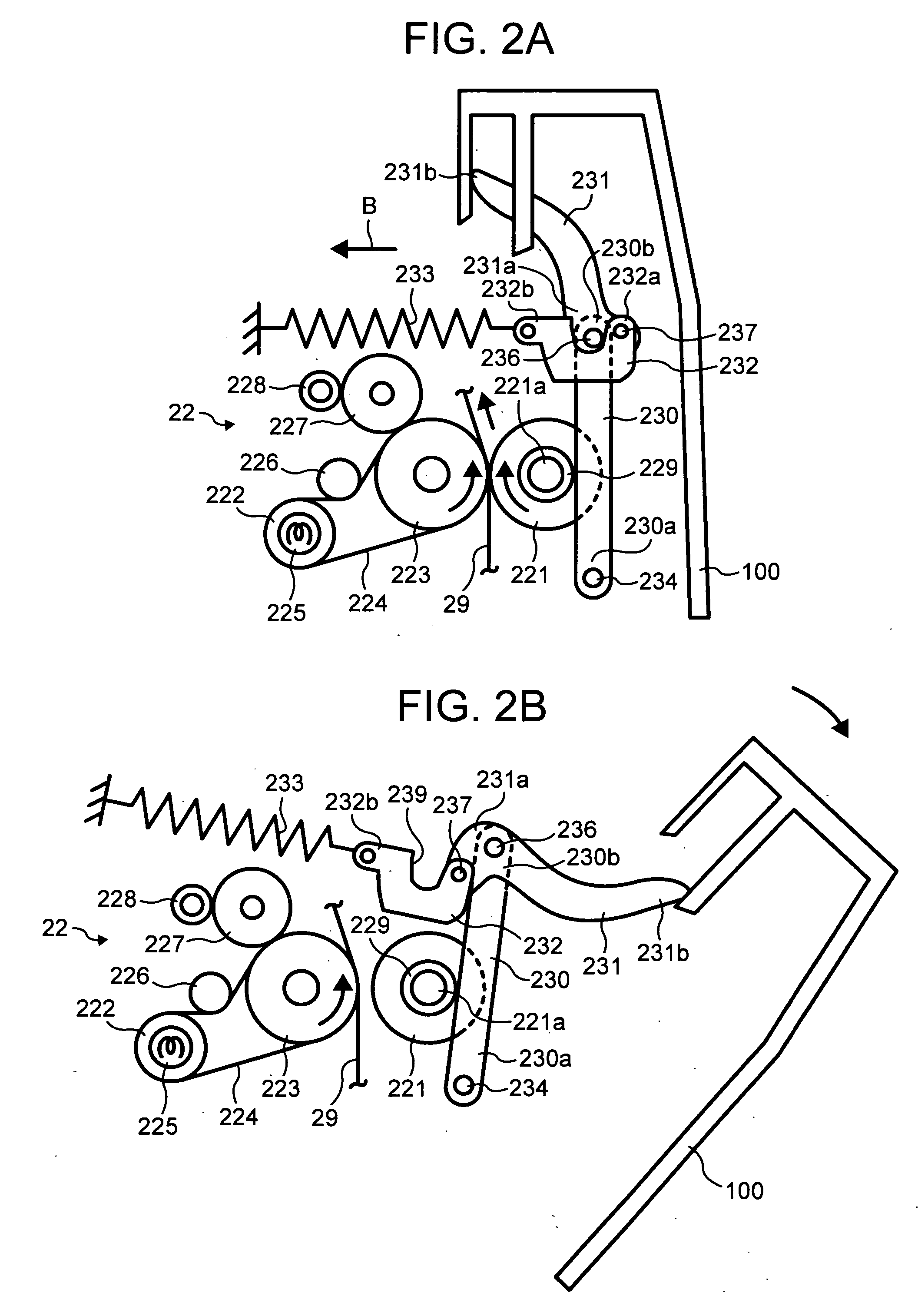
[0022]FIG. 1 illustrates a basic configuration of a printer 1 as one of examples of an image forming system. The printer 1 may be arranged at the lower part of the image forming system. The printer 1 includes a paper storage section 2, an image forming section 3, a fixing apparatus 22, a paper holding section 36, a toner supply section 9 and a cover 100. The paper storage section 2 includes a paper cassette 28 ...


PUM


Abstract

An image forming system includes an image forming mechanism and a fixing mechanism. The fixing mechanism includes first and second fixing members configured to face each other to hold recording materials, a lock member, a pressuring lever, a pressure release lever and an elastic member. The pressure release lever turns between a lock position for a regular operation mode and a release position. The elastic member pulls the lock member capturing the pressuring lever to apply pressure to the first and second fixing members at the far end from the instantaneous center of the pressuring lever at the lock position.

Description

[0001] This patent application claims priority from Japanese patent application, No. 2004-194834, filed on Jun. 30, 2004 in the Japan Patent Office, the entire contents of which are incorporated by reference herein. BACKGROUND OF THE INVENTION [0002] 1. Field of the Invention [0003] The present invention generally relates to an apparatus for image forming, and more particularly to an apparatus for image forming which is capable of applying a high fixing-nip pressure easily releasable when a recording sheet is stuck in a fixing mechanism. [0004] 2. Discussion of the Background [0005] A background image forming system that uses an electrophotographic method forms an electrostatic latent image on a photosensitive surface of an image support member (i.e., a photosensitive member) and develops the electrostatic latent image into a visible image using a developer including toner. Then, the background image forming system transfers the developed toner image onto a recording material such a...

Claims


Application Information

Patent Timeline
Patent Type & Authority Applications(United States)
IPC IPC(8): G03G15/20
CPCG03G15/2035
Inventor SHINSHI, AKIRA
Owner RICOH KK
Why Eureka
Try Eureka