

Electrical power contacts and connectors comprising same
- Summary
- Abstract
- Description
- Claims
- Application Information
AI Technical Summary
Benefits of technology
Problems solved by technology
Method used
Image

Examples
Embodiment Construction
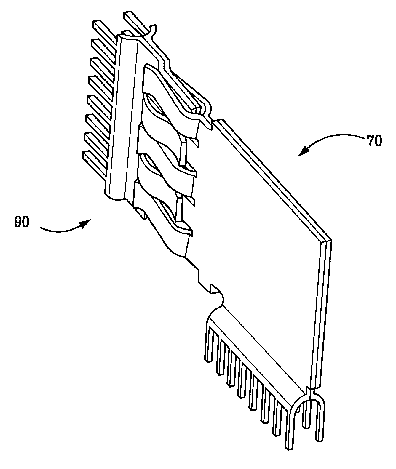
[0004] The present invention provides power contacts for use in an electrical connector. In accordance with one preferred embodiment of the present invention, there has now been provided a power contact including a first plate-like body member, and a second plate-like body member stacked against the first plate-like body member so that the first and second plate-like body members are touching one another along at least a portion of opposing body member surfaces.
[0005] In accordance with another preferred embodiment of the present invention, there has now been provided a power contact including juxtaposed first and second plate-like body members that define a combined plate width. The first body member includes a first terminal and the second body member includes a second terminal. A distance between respective distal ends of the first terminal and the second terminal is greater than the combined plate width.
[0006] In accordance with yet another preferred embodiment, there has now ...
PUM
 Abstract
Description
Claims
Application Information