Shielded cage assembly for electrical connectors

a technology of shielding cage and electrical connector, which is applied in the direction of coupling device connection, coupling protective earth/shielding arrangement, electrical apparatus, etc., can solve the problems of difficult to achieve objectives, problems in the design and manufacture of such systems, etc., and achieve the effect of improving emi capability

Active Publication Date: 2006-01-05
MOLEX INC
View PDF14 Cites 89 Cited by
  • Summary
  • Abstract
  • Description
  • Claims
  • Application Information

AI Technical Summary

Benefits of technology

[0014] Still a further aspect or object of the present invention is to provide a shielded cage assembly for SFP style connectors for holding several modular transceivers and that provides improved EMI capability.
[0018] Another feature of the invention is the provision of stamped and formed sheet metal components without requiring plastic components so as to provide good structural integrity and EMI shielding.

Problems solved by technology

Having such cages readily accommodate the connector array needed for a particular application, while providing excellent EMT protection, are objectives not easily achieved, especially given the smaller desired sizes of cages for applications.
Problems have been encountered in the design and manufacturability of such systems.
One of the problems involves providing a system wherein the connector modules can be mounted above the mother board in arrays and spacings than can vary with the application, such as for specific routers or servers or other equipment.

Method used


Image

  • Shielded cage assembly for electrical connectors
  • Shielded cage assembly for electrical connectors
  • Shielded cage assembly for electrical connectors

Examples


Embodiment Construction

[0033] As required, detailed embodiments of the present invention are disclosed herein; however, it is to be understood that the disclosed embodiments are merely exemplary of the invention, which may be embodied in various forms. Therefore, specific details disclosed herein are not to be interpreted as limiting, but merely as a basis for the claims and as a representative basis for teaching one skilled in the art to variously employ the present invention in virtually any appropriate manner.

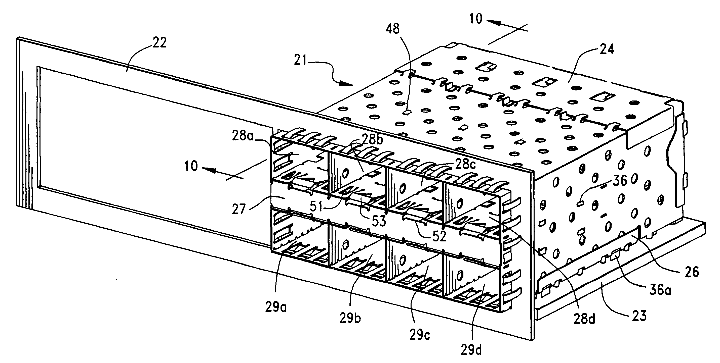
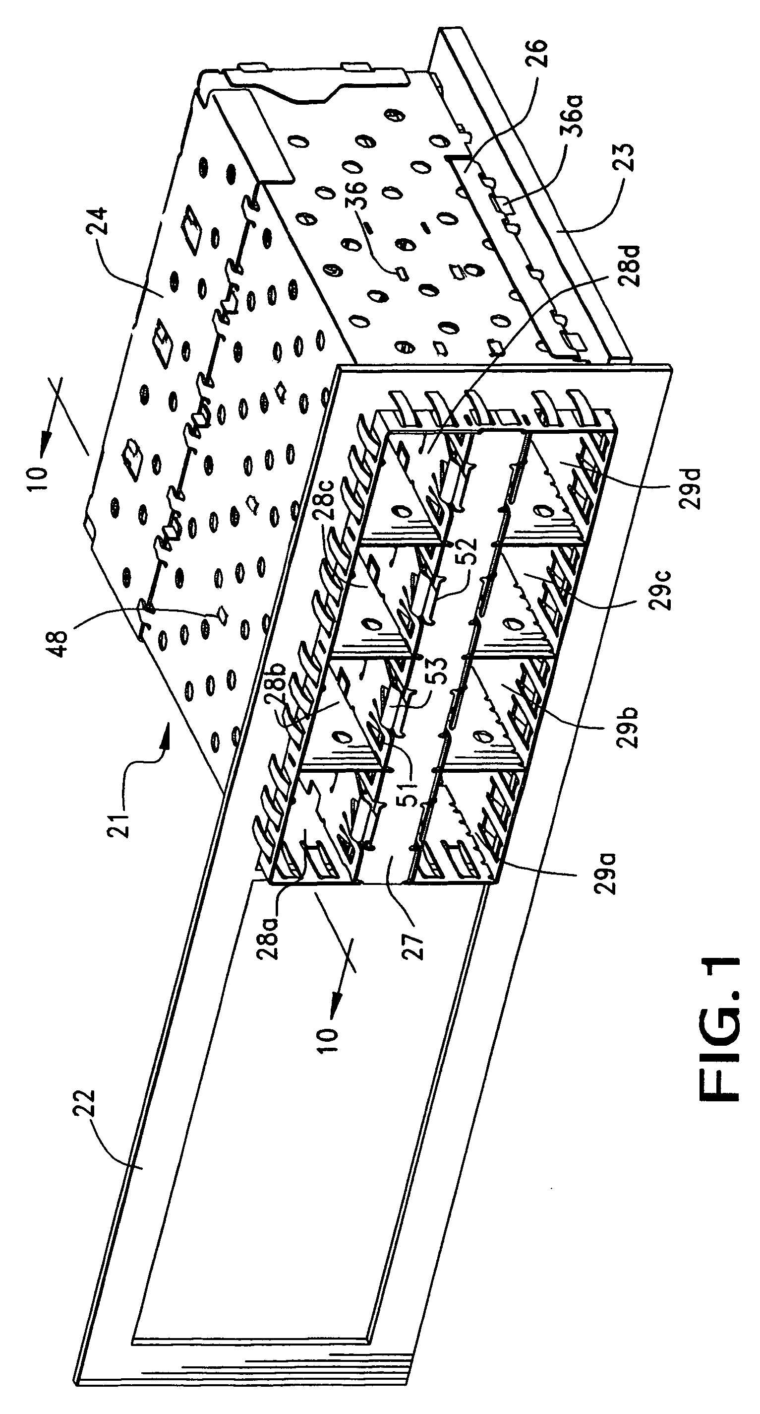
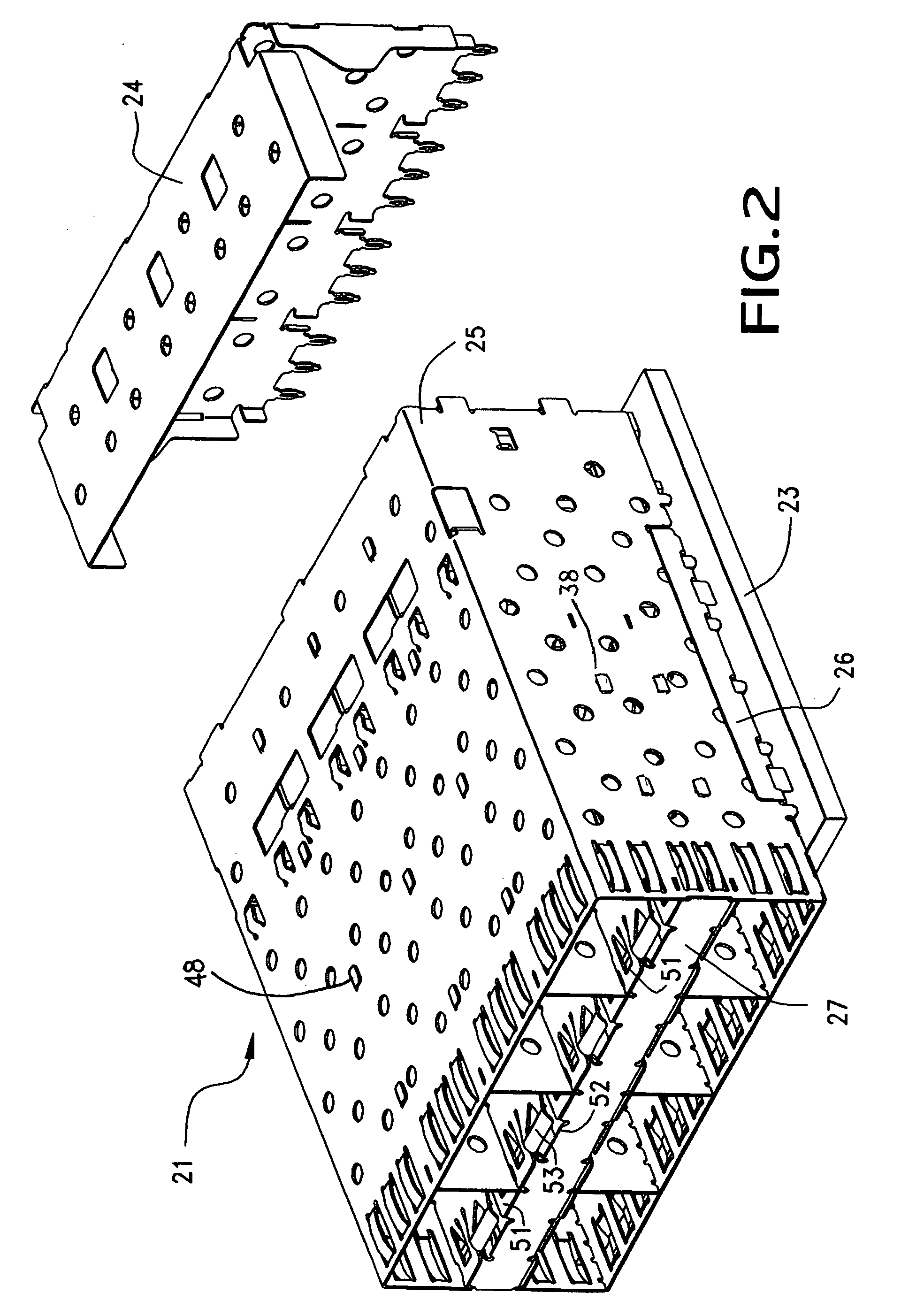
[0034] Referring to the drawings in greater detail, and first to FIG. 1 and FIG. 2, a preferred cage assembly constructed in accordance with the principles of the present invention is illustrated generally at 21, and is illustrated in combination with the face plate 22 of an electronic device having circuit board and connector components, such as server, router or the like. A typical circuit board 23 also is illustrated which supports both electrical components and the cage assembly 21. The cage ...


PUM


Abstract

An integrated wall stacked shielded cage assembly is provided for electrical connectors. The cage assembly has multiple bays for receiving electrical components. At least two arrays of bays are provided, and the arrays are separated by an intervening space. Assembly is carried out with a plurality of spacers which interlock with a plurality of intermediate walls, and cover structures are provided in order to complete EMI shielding.

Description

REFERENCE TO RELATED APPLICATIONS [0001] This application claims priority of prior U.S. provisional patent applications No. 60 / 584,420, filed Jun. 30, 2004 and No. 60 / 639,496, filed Dec. 23, 2004. BACKGROUND OF THE INVENTION [0002] This invention generally relates to electrical connectors, more particularly to small sized electrical connectors having a stacked arrangement. The illustrated connectors provide an adapter cage assembly for mounting multiple connectors in a stacked array of connector sets with one connector set mounted above another connector set. The invention includes multiple components which interlock together into a cage assembly for holding multiple modular transducers in place. [0003] Electrical connectors are used in a wide variety of applications ranging from simple connecting interfaces between hard conductor wiring to more sophisticated applications involving such components as printed circuit boards, flat flexible cables and optical fibers. Basically, electri...

Claims


Application Information

Patent Timeline
Patent Type & Authority Applications(United States)
IPC IPC(8): H01R13/648H01R12/71
CPCH01R13/518H01R12/716H05K9/0058H01R13/65802H01R13/6582H01R13/659
Inventor LONG, JERRY A.
Owner MOLEX INC
Why Eureka
Try Eureka