Ramrod handle

a ramrod and handle technology, applied in the field of improved handles, can solve the problems of not being universally adaptable to use and many prior art handles can function, and achieve the effect of convenient storage and easy removal from and attaching to the ramrod

Inactive Publication Date: 2006-01-12
OX YOKE ORIGINALS
View PDF10 Cites 9 Cited by
  • Summary
  • Abstract
  • Description
  • Claims
  • Application Information

AI Technical Summary

Benefits of technology

[0007] Among the objects of the invention is the provision of a ramrod handle which is easily removable from and attachable to the ramrod, c...

Problems solved by technology

In addition, many prior art handles can function only with a particular ramrod or w...

Method used


Image

  • Ramrod handle
  • Ramrod handle
  • Ramrod handle

Examples


Embodiment Construction

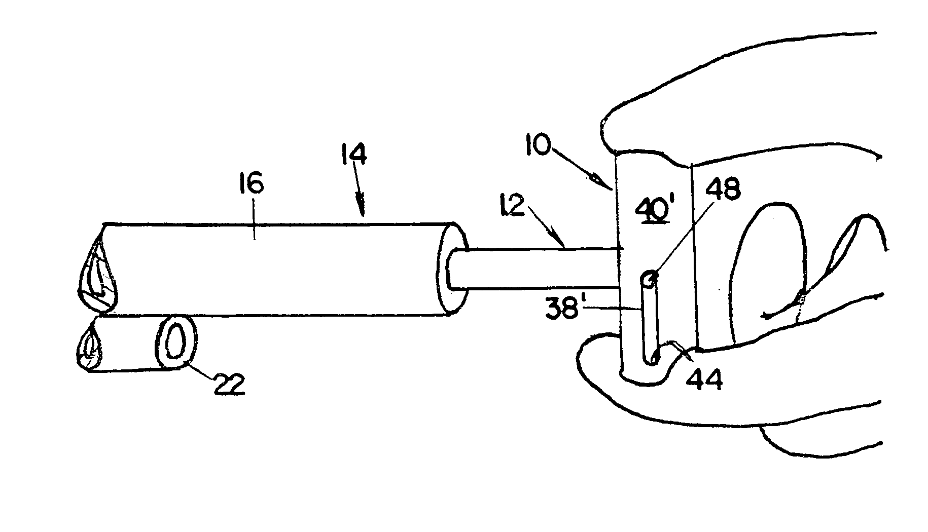
[0030] Referring first to FIGS. 7-9, a handle embodying a preferred form of the invention is generally indicated by 10; a ramrod, shown fragmentarily, is generally indicated by 12; and a firearm, also shown fragmentarily, is generally indicated by 14.

[0031] Firearm 14 includes a barrel 16 having a bore 18 which terminates at an outer free end in a muzzle 20, the barrel having a storage sleeve 22 formed integrally therewith.

[0032] Storage sleeve 22 is spaced rearwardly of muzzle 20, and is disposed in parallel relationship to bore 18 of barrel 16 for receiving and storing ramrod 12 therein, in a manner as shown in FIG. 8.

[0033] Ramrod 12, which is of cylindrical cross section and has a diameter substantially similar to that of bore 18 of firearm 14, is fabricated from thermoplastic, or metal, or wood, or composite material.

[0034] Handle 10 is fabricated from thermoplastic, or metal, or wood, or composite material, is substantially cylindrical in cross-section, and is of appropria...


PUM


Abstract

A handle for the ramrod of a muzzle loading firearm which has storage means for the ramrod on its barrel is releasably attached to the ramrod and movable between a first locked position wherein it is coaxial with the ramrod and a second locked position wherein it is perpendicular to the ramrod, the handle having a seating surface which allows it to be stored on the firearm barrel regardless of the cross sectional shape of the firearm barrel.

Description

FIELD OF THE INVENTION [0001] The invention relates to an improved handle for ramrods of the type as used with firearms of the muzzle-loading type. BACKGROUND OF THE INVENTION [0002] With muzzle-loading firearms, a ramrod is provided comprising a cylindrical tool having a diameter substantially similar to the bore of the barrel of the firearm. In use, the ramrod is inserted into the open end or muzzle of the barrel of the firearm for several purposes such as: tamping powder and a bullet previously inserted into the barrel; or, with the addition of appropriate removal means, removing a bullet or other unwanted material lodged in the barrel; or, with the addition of appropriate cleaning means, cleaning the bore of the barrel. [0003] In view of the relatively small diameter of most ramrods, a handle for ramrod manipulation is a virtual necessity for accomplishing either the tamping function, or the removal function, or the cleaning function. [0004] A wide variety of ramrod handles is d...

Claims


Application Information

Patent Timeline
IPC IPC(8): F41A15/00F41A29/00
CPCF41C9/08F41A29/00
Inventor LEE, ROBERT C.DESMARAIS, RONALD
Owner OX YOKE ORIGINALS
Why Eureka
Try Eureka