Vial with hinged cap and method of making same

Inactive Publication Date: 2006-01-12
POLYTOP
View PDF61 Cites 18 Cited by
  • Summary
  • Abstract
  • Description
  • Claims
  • Application Information

AI Technical Summary

Benefits of technology

[0020] The Applicants have speculated that the sealing configuration of the present oval vial behaved differently than a cylindrical vial and more specifically that the flexible channel walls in the lid were being flexed outwardly and permanently deformed during seating of the lid on the body (if the plastic was too warm). Thus, that the channel walls were thus not providing the proper compressive force to maintain a

Problems solved by technology

Despite the well-known advantages of sealing a cap onto a body while the plastic is still warm, the present vial

Method used


Image

  • Vial with hinged cap and method of making same
  • Vial with hinged cap and method of making same
  • Vial with hinged cap and method of making same

Examples


Example

[0041] A. The Vial

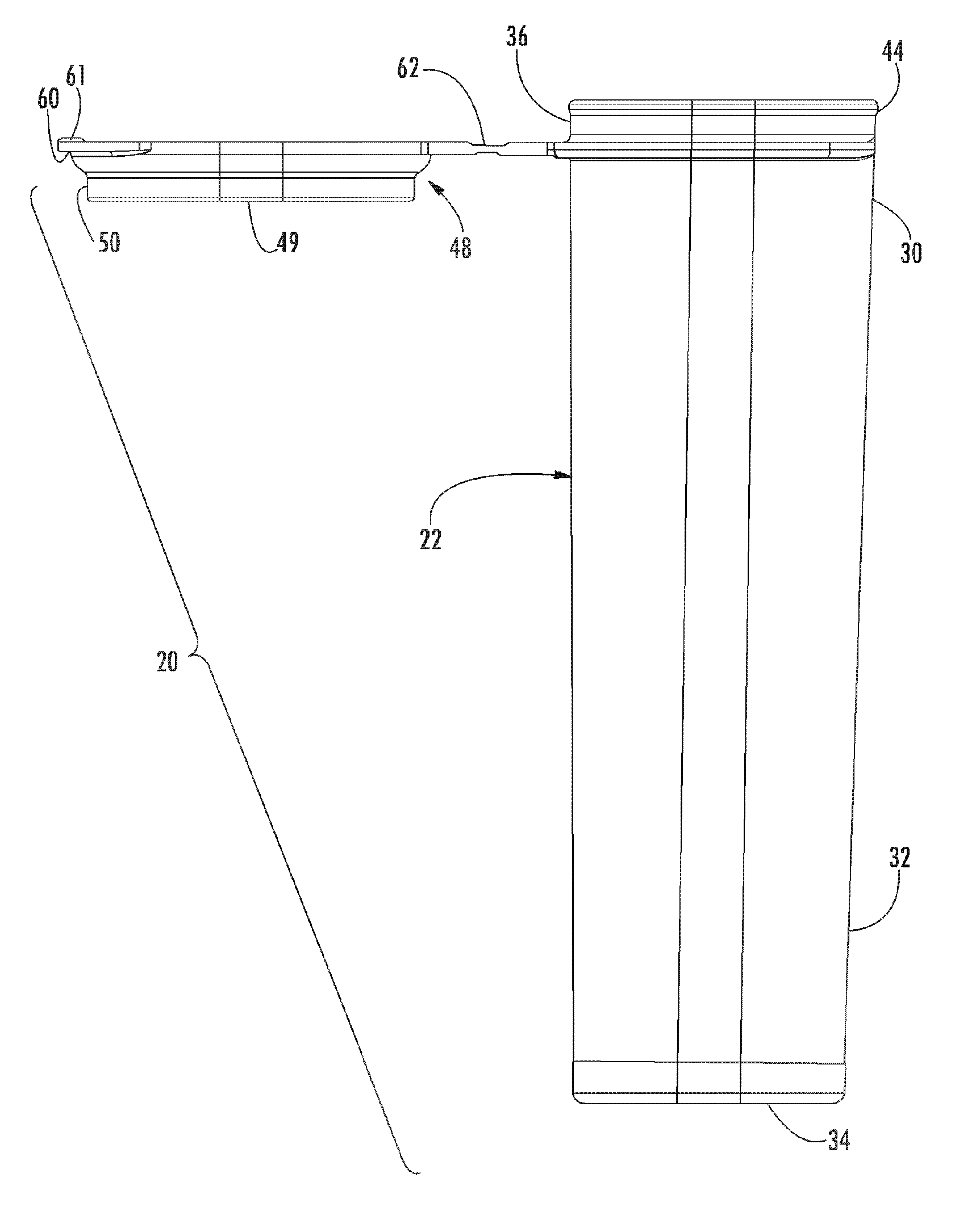
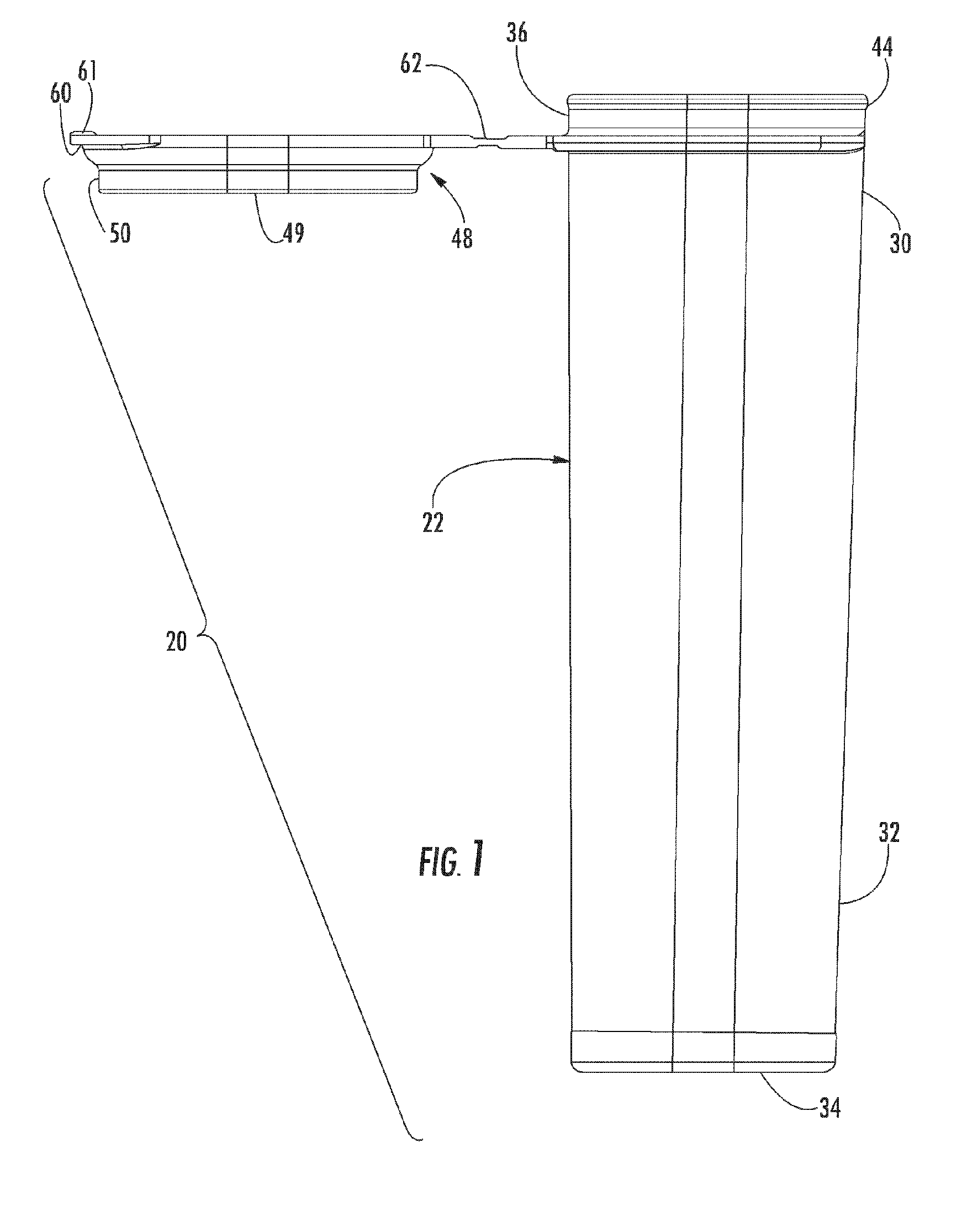
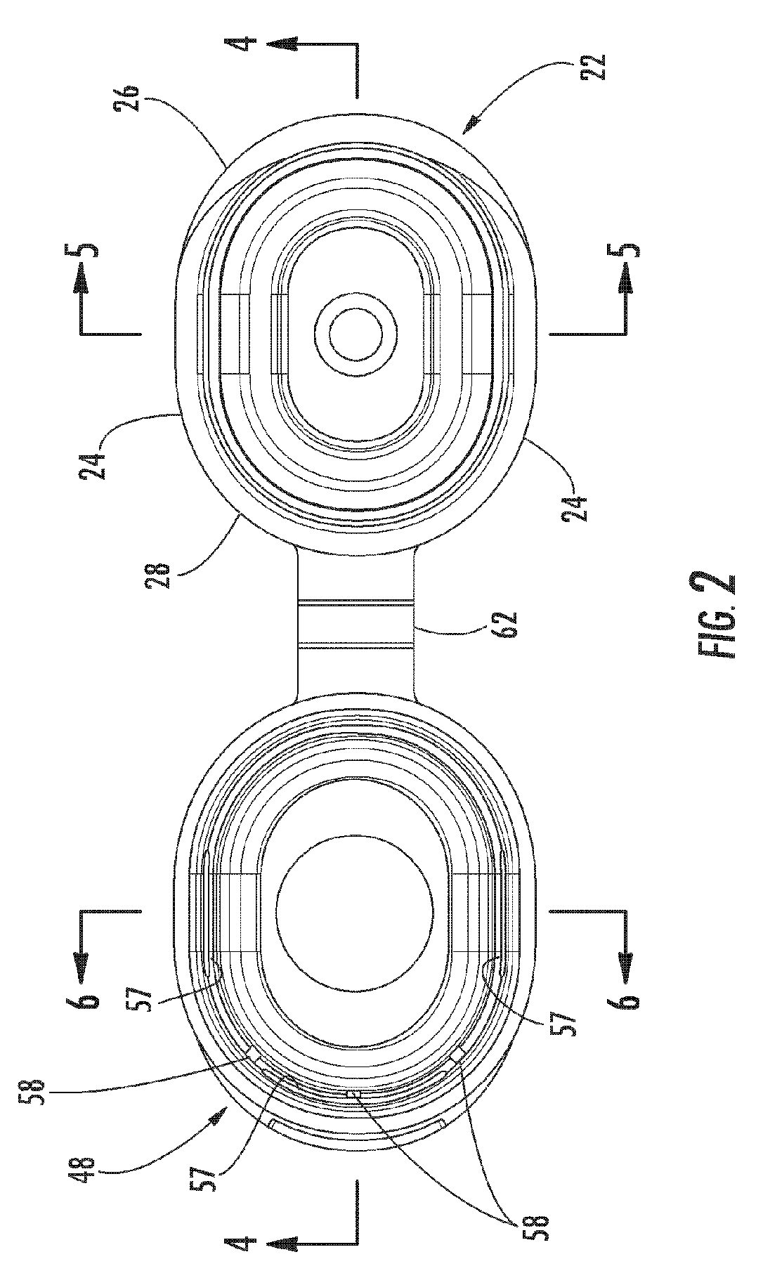
[0042] Referring to FIGS. 1-10, the dispensing vial of the present invention, shown generally at 20, includes a vial body 22 with an dispensing orifice 46 and a vial lid 48 integrally connected to the vial body 22 by a living hinge structure 62. The vial body 22 and vial lid 48 are substantially oval or elliptical in shape having a short linear side 24 and arcuate front surface 26 and an arcuate rear surface 28 (See FIGS. 2 and 3 for oval shape). Although the preferred embodiment of the present invention has an oval shape cross-section, the present invention can be applied to other vial geometries, such as square, circular or triangular to name a few, and the present invention should not be limited as such.

[0043] In many ways, the dispensing vial 20 is identical to that of a dispensing closure (not shown). The main exception being that the lower body portion 30 of the dispensing vial 20 is closed by a bottom surface 34, while the skirt (not shown) of the dispensi...


PUM

PropertyMeasurementUnit
Temperatureaaaaaaaaaa

Abstract

A method of making a dispensing vial from a plastic material. The vial includes a vial body, a vial lid and a living hinge structure connecting the vial lid to the vial body. The dispensing vial is molded and removed from the mold still warm. The living hinge structure is flexed while the plastic is still warm. Thereafter, the sealing surfaces are actively cooled to cause the plastic to fully set, and finally the vial lid is closed shut.

Description

CROSS-REFERENCE TO RELATED APPLICATION [0001] This application is related to and claims priority from earlier filed U.S. Provisional Application No. 60 / 587,276, filed Jul. 12, 2004, the contents of which are incorporated herein by reference.BACKGROUND OF THE INVENTION [0002] 1. Field of the Invention [0003] The present invention relates to containers and vials having hinged closures that maintain a seal. More specifically, the present invention relates to a vial having an integrally hinged cap and a method for manufacturing the vial. [0004] 2. Background of the Related Art [0005] Containers and vials having hinged closures are well known in the art. In this regard, there are dozens of patents that describe various different configurations of dispensing closures and vials with hinged caps, as well as different methods for manufacturing such products. The U.S. patents to Hayberg, U.S. Pat. No. 4,351,630; Wilson et al, U.S. Pat. No. 4,220,248; Hazzard, U.S. Pat. No. 4,377,247; Eitzinge...

Claims


Application Information

Patent Timeline
IPC IPC(8): B29C45/00B29C45/72B29D99/00B65D43/16
CPCB29C45/006B29C45/0081B29C45/7207B29C65/58B29C65/7861B29L2031/565B29C66/91411B29L2031/772B65D43/162B29C66/542B29C66/549B29C66/91216B29C66/91221B29L2031/712B29C66/8242B29C66/8322
Inventor JOHNSON, JOSEPH E.BRANNON, PATRICK J.SKILLIN, CLIFFORD W.
Owner POLYTOP
Why Eureka
Try Eureka