Suction valve assembly for alternative compressor

Inactive Publication Date: 2014-11-27
EMBRACO IND DE COMPRESSORES E SOLUCOES EM REFRIGERACAO LTDA
View PDF2 Cites 5 Cited by
  • Summary
  • Abstract
  • Description
  • Claims
  • Application Information

AI Technical Summary

Benefits of technology

[0017]In this sense, one object of the present invention is to provide suction valves containing actuation (sealing/opening regions) independe

Problems solved by technology

The concept in which a single valve acts on more than one orifice is undesirable from the point of view of sealing and dynamics.
In order that sealing is effective, the valve seat on the orifice edge should be plane; nevertheless, as the valve deforms within the orifice, such configuration is not effectively attained when 2 epicenters of deformation are present, leading to leakages.
As far as dynamics is concerned, a large body area is required for valve stability, thereby promoting an increase in mass and rigidity of the valve, rendering it slow.
However, configurations, as disclosed in said U.S. Pat. No. 2,725,183, do not make a better use of the solutions provided by multi-orifice.
Another visible drawback of this present configuration is the obstruction of the centr

Method used


Image

  • Suction valve assembly for alternative compressor
  • Suction valve assembly for alternative compressor
  • Suction valve assembly for alternative compressor

Examples


Example

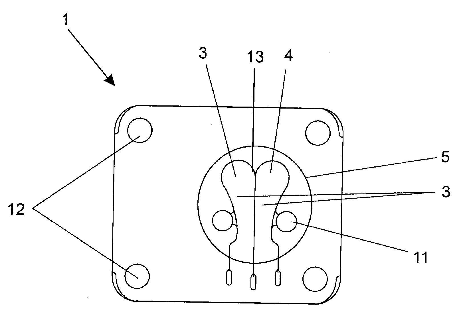
[0026]In accordance with the main objects of the present invention, a new suction valve assembly for alternative compressor, whose arrangement of its members makes it particularly suitable for a single suction chamber (not shown) comprising at least independent suction orifices (not shown), is disclosed.

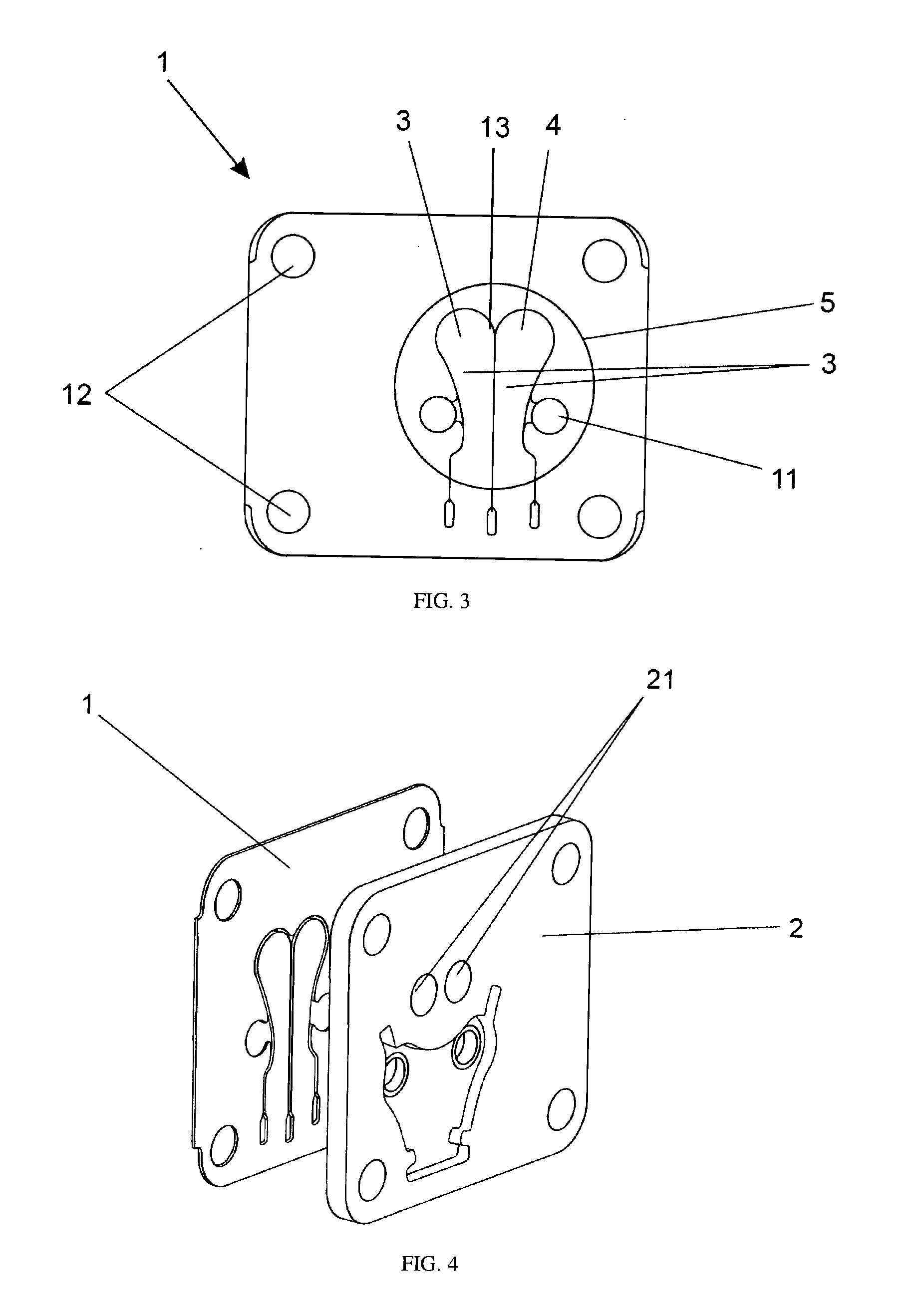
[0027]Therefore, said suction valve assembly comprises at least two sealing / opening edges for independent suction orifices. Especially, the number of sealing / opening edges of the suction valve assembly is similar to the number of independent suction orifices 21 housed in valve plate 2 of an alternative compressor.

[0028]By this way, and based on such concepts, reference is made to FIGS. 3 and 4 in order to give an detailed description of the preferred embodiment of the present invention. It is herein pointed out that in this description, sealing / opening edges of suction valves are designated “functional edges.”

[0029]According to the preferred embodiment of the present invention, the s...


PUM


Abstract

The present invention refers to a suction valve assembly for alternative compressors. Said suction valve assembly comprises at least two suction valves (3) independent from one another and disposed at one same blade (1), wherein each of said suction valves (3) comprises a functional edge (4) intended for a sole suction orifice (21) of the valve plate. Said suction valves (3) are separated from one another by at least one through slit (13).

Description

FIELD OF THE INVENTION [0001]The present invention refers to a suction valve assembly for alternative compressor, and, more specifically, to a suction valve assembly formed into a sole blade and particularly suitable for a compression chamber provided with at least two independent suction orifices.BACKGROUND OF THE INVENTION[0002]Alternative compressors comprising machines and / or devices capable of altering the pressure of a working fluid as well as pumping it are known from those skilled in the art. In this sense, and specifically speaking, alternative compressors are capable of altering the pressure of a working fluid by the controlled alteration of the volume of a compression chamber, which is usually defined by a cylindrical chamber suitable for receiving working fluid and a moving piston. Therefore, the compression chamber volume is alternatively altered (decreased and increased) in function of the displacement, in its interior, of the moving piston.[0003]It should be point out...

Claims


Application Information

Patent Timeline
IPC IPC(8): F04B39/10
CPCF04B39/1073F04B39/108F16K15/16Y10T137/7859
Inventor PIROVANO, MOACIRRODRIGUES, TADEU TONHEIROGAERTNER, EDUARDO LUISRAMSDORF, ROBERTO
Owner EMBRACO IND DE COMPRESSORES E SOLUCOES EM REFRIGERACAO LTDA
Why Eureka
Try Eureka