Apparatus for and method of scaling a scanning angle and image projection apparatus incorporating the same

a technology of which is applied in the field of apparatus for scaling scanning angle and image projection apparatus incorporating the same, can solve the problems of limited size, high price of display systems that can reproduce high-resolution video images, and insufficient brightness

Active Publication Date: 2006-01-12
SAMSUNG ELECTRONICS CO LTD
View PDF8 Cites 73 Cited by
  • Summary
  • Abstract
  • Description
  • Claims
  • Application Information

AI Technical Summary

Benefits of technology

The present invention provides a laser scanning apparatus with multiple elliptical mirrors and scanners. The elliptical mirrors have two focal points, and the scanners are placed at both focal points. This arrangement allows the elliptical mirrors to reflect scanned light beams from one scanner to another, resulting in a wider scanning angle.

Problems solved by technology

The technical problem addressed in this patent text is the need to increase the scanning angle of a MEMS scanner without compromising the size of the mirror. This would allow for a clearer picture and better manufacturability for large, high-resolution, rear or front projection TVs.

Method used


Image

  • Apparatus for and method of scaling a scanning angle and image projection apparatus incorporating the same
  • Apparatus for and method of scaling a scanning angle and image projection apparatus incorporating the same
  • Apparatus for and method of scaling a scanning angle and image projection apparatus incorporating the same

Examples


Embodiment Construction

[0034] Reference will now be made in detail to the embodiments of the present invention, examples of which are illustrated in the accompanying drawings, wherein like reference numerals refer to the like elements throughout. The embodiments are described below to explain the present invention by referring to the figures.

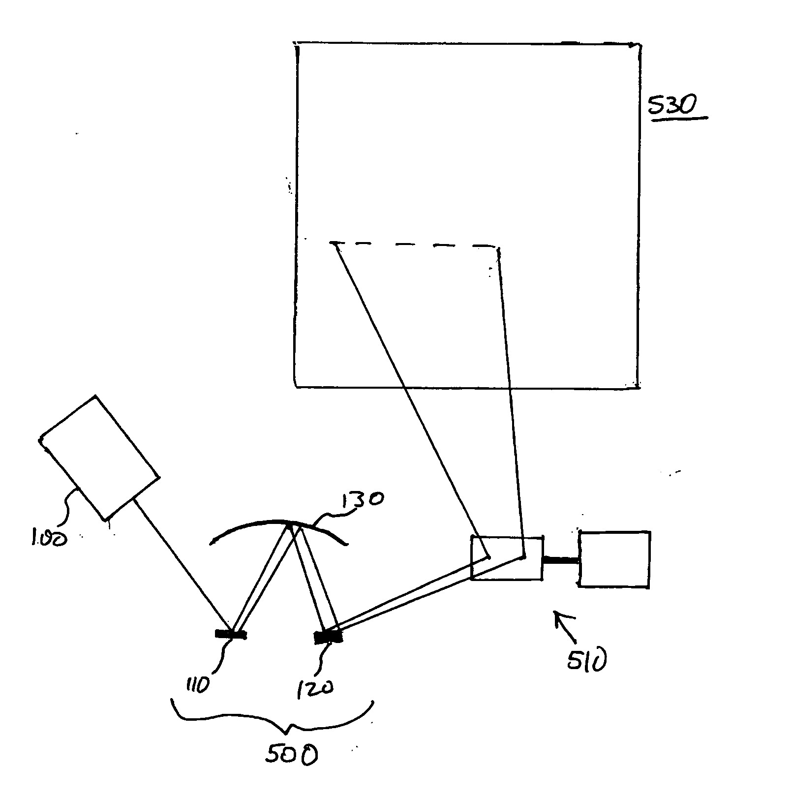
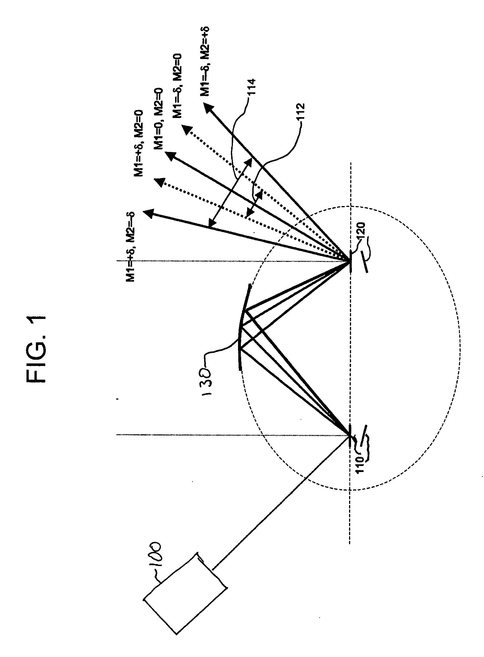
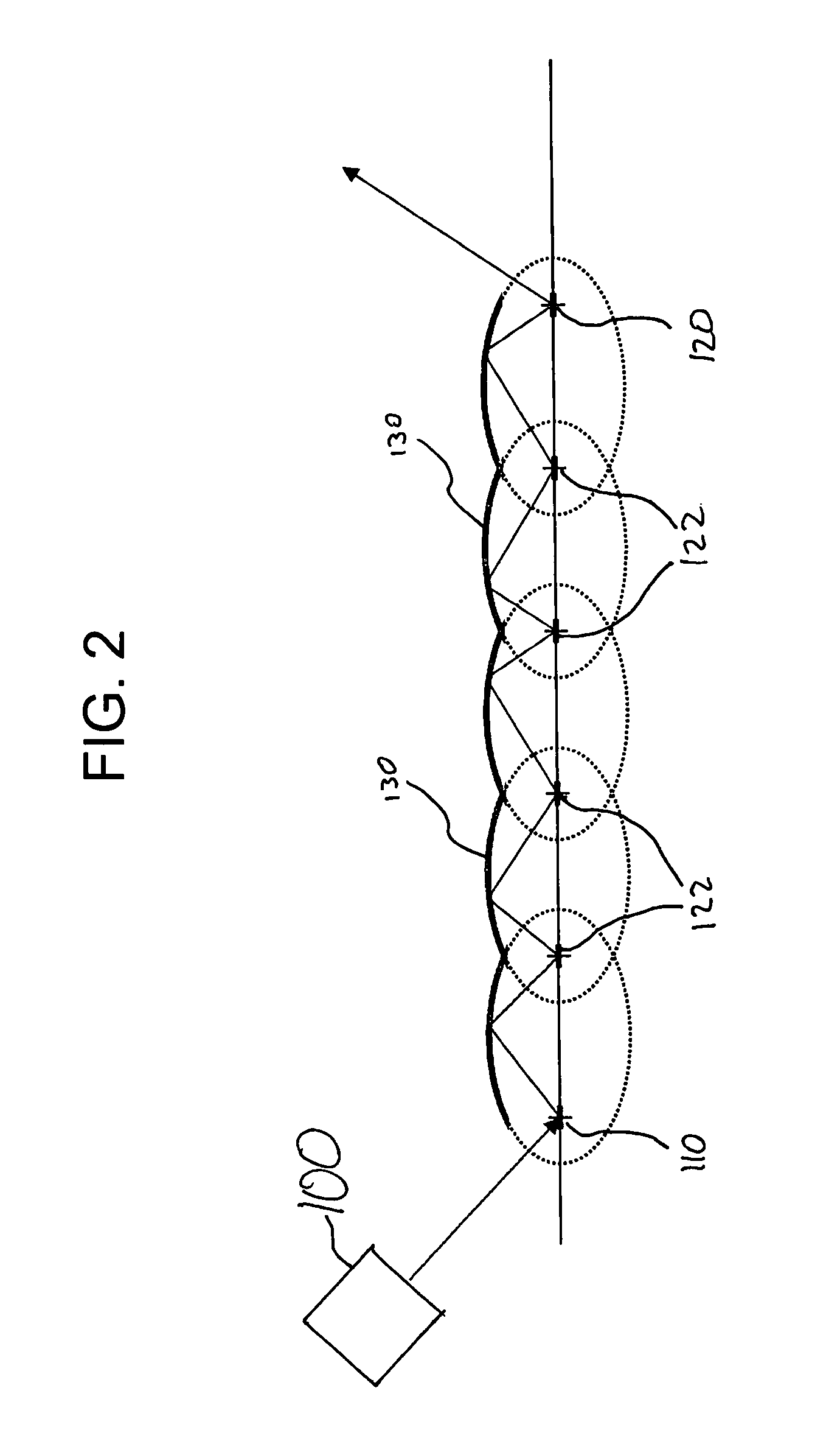
[0035]FIG. 1 is a schematic view of an embodiment of an optical scanner apparatus that has a scalable scanning angle. Referring to FIG. 1, the optical scanner apparatus comprises a first optical scanner 110, a second optical scanner 120 and an elliptical mirror 130. The first optical scanner 110 and the second optical scanner 120 are disposed at respective foci of the elliptical mirror 130. The first optical scanner 110 and the second optical scanner 120, respectively, oscillate a reflective surface through a predetermined range. In an aspect, the first optical scanner 110 and the second optical scanner 120 are microelectromechanical system (MEMS) optical scanners.

[...


PUM


Abstract

A scalable laser scanning angle apparatus and method of scaling a scanning angle using MEMS devices and elliptical mirrors includes disposing a first scanner at one focal point of an elliptical mirror and scanning the emitted light beam in a first direction at a first scanning angle toward a concave surface of the elliptical mirror such that the scanned light beam is directed toward the second focal point of the elliptical mirror, and scanning the light beam from the concave surface of the elliptical mirror in a second direction at a second scanning angle using a second scanner, wherein the second scanner outputs the light beam across a system scanning angle which corresponds to a combination of the first scanning angle and the second scanning angle. The scanning angle is scalable by repeatedly scanning the light beam at corresponding focal points of a predetermined number of elliptical mirrors, wherein the total scanning angle is scaled by a multiple of a number of times the light beam is scanned.

Description


Claims


Application Information

Patent Timeline
Owner SAMSUNG ELECTRONICS CO LTD
Why Eureka
Try Eureka