Zoom lens system

a zoom lens and zoom technology, applied in the field of zoom lens systems, can solve the problems of difficult manufacturing and unsatisfactory correction of aberration, and achieve the effect of easy manufacturing and high optical performan

Active Publication Date: 2006-01-12
NIKON CORP
View PDF4 Cites 15 Cited by
  • Summary
  • Abstract
  • Description
  • Claims
  • Application Information

AI Technical Summary

Benefits of technology

[0010] The present invention is made in view of the aforementioned problems and has an object to provide a zoom lens system having compactness of about the size of a single focal length normal lens, small number of lens elements, zoom ratio of about 2.9, and high optical performance with being easy to be manufactured.

Problems solved by technology

However, the zoom lens disclosed in Japanese Patent Application Laid-Open No. 55-60931 is bulky and correction of aberration is not satisfactory.
The zoom lenses disclosed in Japanese Patent Application Laid-Open Nos. 8-334694 and 2002-6214 have a large number of lens elements and are difficult to be manufactured.
Moreover, the zoom lenses disclosed in Japanese Patent Application Laid-Open Nos. 9-171140 and 2000-2837 have a large number of lens elements, so they are bulky.

Method used


Image

  • Zoom lens system
  • Zoom lens system
  • Zoom lens system

Examples


first embodiment

[0048] Basic construction of the zoom lens according to the present invention is going to be explained below.

[0049] Generally, in a negative-positive two-group zoom lens, a second lens group having positive refractive power acts as a master lens of a whole zoom lens system. Usually by the effect of the second lens group, an air space (a necessary minimum air space for varying lens group positions) between the first lens group and the second lens group has to be secured for zooming with securing the back focal length. In consideration of reducing the size and manufacturing cost of the zoom lens system, it becomes further necessary to reduce the size and the number of lens elements of the second lens group as much as possible.

[0050] There are such lens types, satisfying these requirements, as an Ernostar type, a modified Triplet type, and a Sonnar type having a basic construction of positive-positive-negative-positive power arrangement. However, the lens having any of these lens typ...

example 1

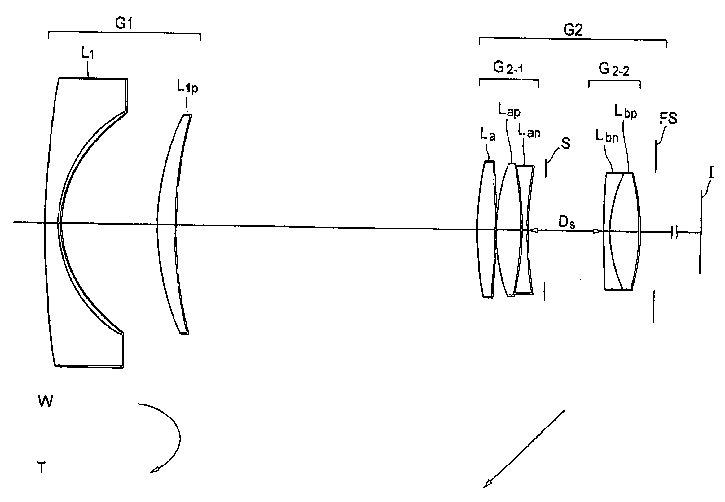
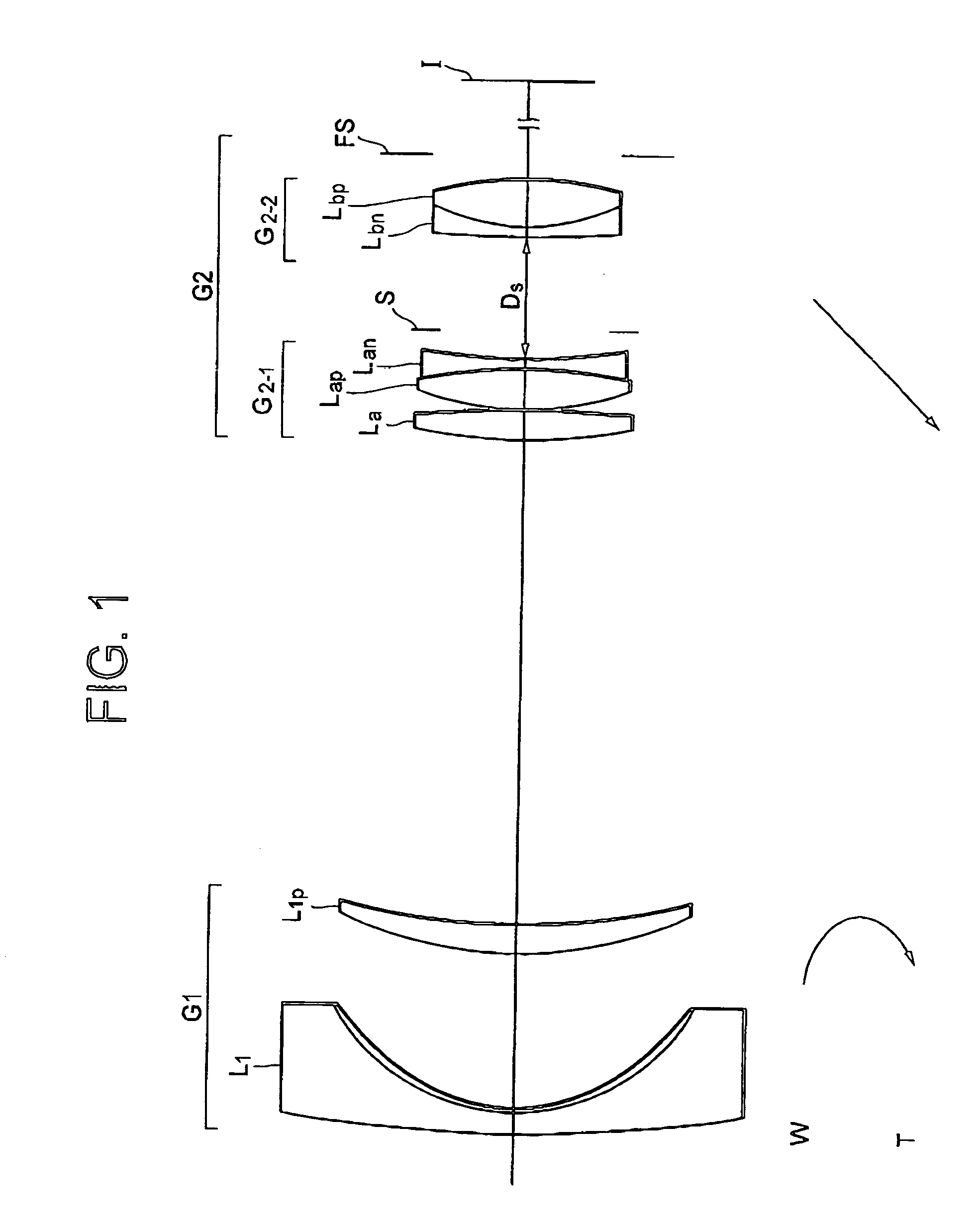
[0077]FIG. 1 is a diagram showing the lens arrangement of a zoom lens system according to Example 1 of the present invention together with movement of each lens group.

[0078] The zoom lens system according to Example 1 is a negative-positive two-group zoom lens system composed of, in order from an object, a first lens group G1 having negative refractive power and a second lens group G2 having positive refractive power.

[0079] The first lens group G1 is composed of, in order from the object, a negative meniscus lens Ll having a convex surface facing to the object, and a positive meniscus lens Llp having a convex surface facing to the object. The negative meniscus lens Ll is a compound lens constructed by glass and resin. Resin is arranged on the image side surface of the lens. The image side surface of the resin is an aspherical surface.

[0080] The second lens group G2 is composed of, in order from the object, a front lens group G2-1, an aperture stop S, a rear lens group G2-2, and a...

example 2

[0096]FIG. 5 is a diagram showing the lens arrangement of a zoom lens system according to Example 2 of the present invention together with movement of each lens group.

[0097] The zoom lens system according to Example 2 is a negative-positive two-group zoom lens system composed of, in order from an object, a first lens group G1 having negative refractive power and a second lens group G2 having positive refractive power.

[0098] The first lens group G1 is composed of, in order from the object, a negative meniscus lens L1 having a convex surface facing to the object, and a positive meniscus lens Llp having a convex surface facing to the object. The negative meniscus lens L1 is a compound lens constructed by glass and resin. Resin is arranged on the image side surface of the lens. The image side surface of the resin is an aspherical surface.

[0099] The second lens group G2 is composed of, in order from the object, a front lens group G2-1, an aperture stop S, a rear lens group G2-2, and a...


PUM


Abstract

An object is to provide a zoom lens system having compactness of about a normal lens, small number of lens elements, a zoom ratio about 2.9, good productivity, and high optical performance. The system includes, in order from the object, a first lens group with negative power and a second lens group with positive power. Zooming is performed by varying a distance between the first lens group and the second lens group. The first lens group includes at least a negative lens and a positive lens. The second lens group includes a front lens group with positive power and a rear lens group with positive power. The front lens group includes a positive lens and a cemented lens constructed by a positive lens cemented with a negative lens. The rear lens group includes a cemented lens constructed by a negative lens cemented with a positive lens. Given conditions are satisfied.

Description

[0001] The disclosures of the following priority applications are herein incorporated by reference: [0002] Japanese Patent Application No. 2003-016603 filed Jan. 24, 2003 and [0003] Japanese Patent Application No. 2004-236077 filed Aug. 13, 2004. BACKGROUND OF THE INVENTION [0004] 1. Field of the Invention [0005] The present invention relates to a zoom lens system. [0006] 2. Related Background Art [0007] Among negative-positive type two-group zoom lenses, there is a zoom lens using an advanced Gauss type lens group as a second lens group having positive refractive power (disclosed, for example, in Japanese Patent Application Laid-Open No. 55-60911) In addition, zoom lenses of this type have been disclosed, for example, in Japanese Patent Application Laid-open Nos. 8-334694, 9-171140, 2000-28:37, and 2002-6214). [0008] However, the zoom lens disclosed in Japanese Patent Application Laid-Open No. 55-60931 is bulky and correction of aberration is not satisfactory. The zoom lenses discl...

Claims


Application Information

Patent Timeline
Patent Type & Authority Applications(United States)
IPC IPC(8): G02B15/14
CPCG02B15/177G02B15/1425
Inventor SATO, HARUO
Owner NIKON CORP
Why Eureka
Try Eureka