Mounting/adjusting mechanism for vision enhancement system

a technology of vision enhancement and mounting mechanism, which is applied in the field of night vision system and video enhanced night vision system, can solve the problems of insufficient degree of freedom of most mounting mechanism of vision enhancement device, and achieve the effect of facilitating optical axes alignmen

Active Publication Date: 2006-01-12
ELBIT SYSTEMS OF AMERICA LLC
View PDF3 Cites 91 Cited by
  • Summary
  • Abstract
  • Description
  • Claims
  • Application Information

AI Technical Summary

Benefits of technology

[0008] The invention generally comprises a mounting assembly for a vision enhancement device and an associated vision enhancement display. The mounting assembly comprises a display mount for holding the vision enhancement display; an arm extending from a fixed end to a free end positionable in front of an eye...

Problems solved by technology

Most vision enhancement device mounting mechanisms, however, do not provide enough degrees of freedom to facilitate optical axes alignment (alignment of the vision enhancement device optical axis OAc to user line of sight LS) and have no provisions for adjusting parallelism between the display and sensor optical axes OAD and OAc or aligning the ...

Method used


Image

  • Mounting/adjusting mechanism for vision enhancement system
  • Mounting/adjusting mechanism for vision enhancement system
  • Mounting/adjusting mechanism for vision enhancement system

Examples


Embodiment Construction

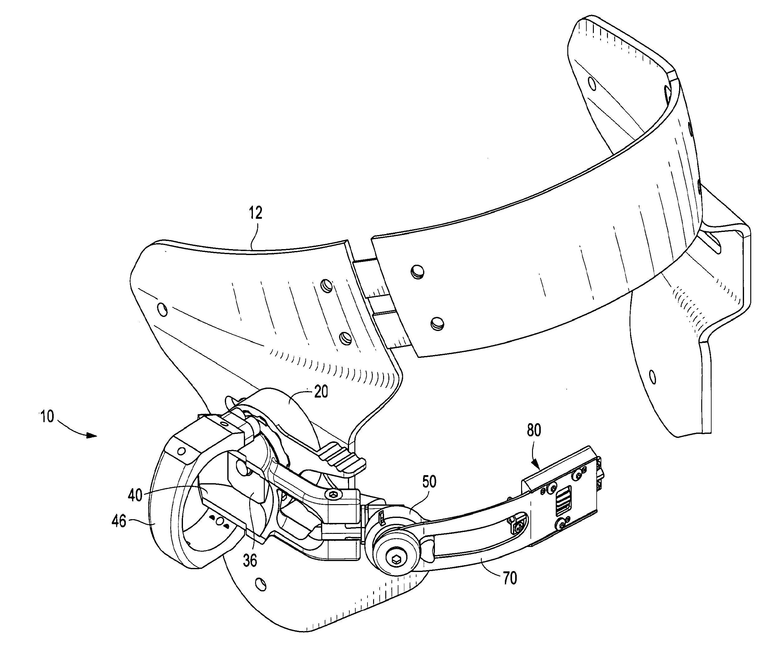
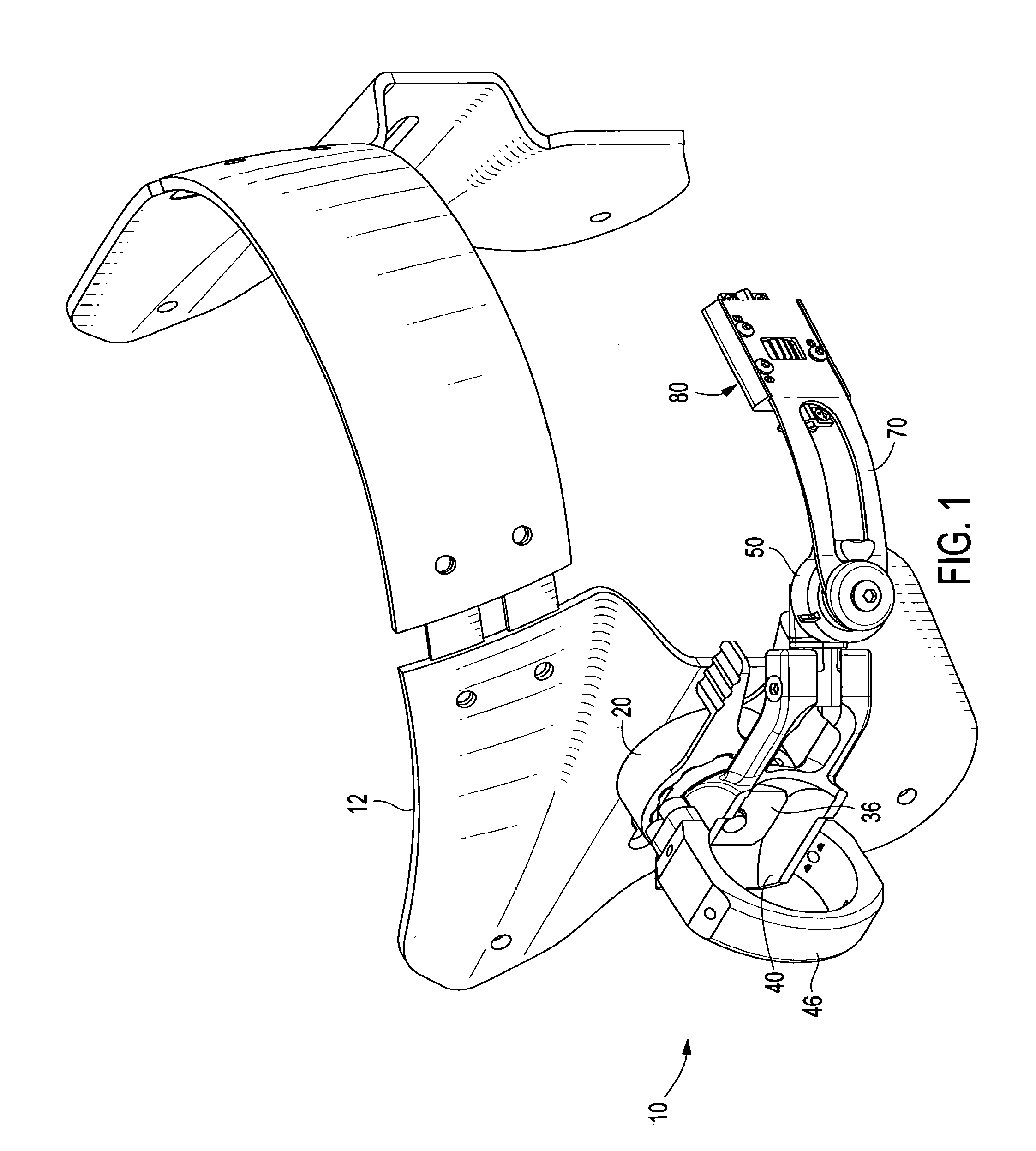
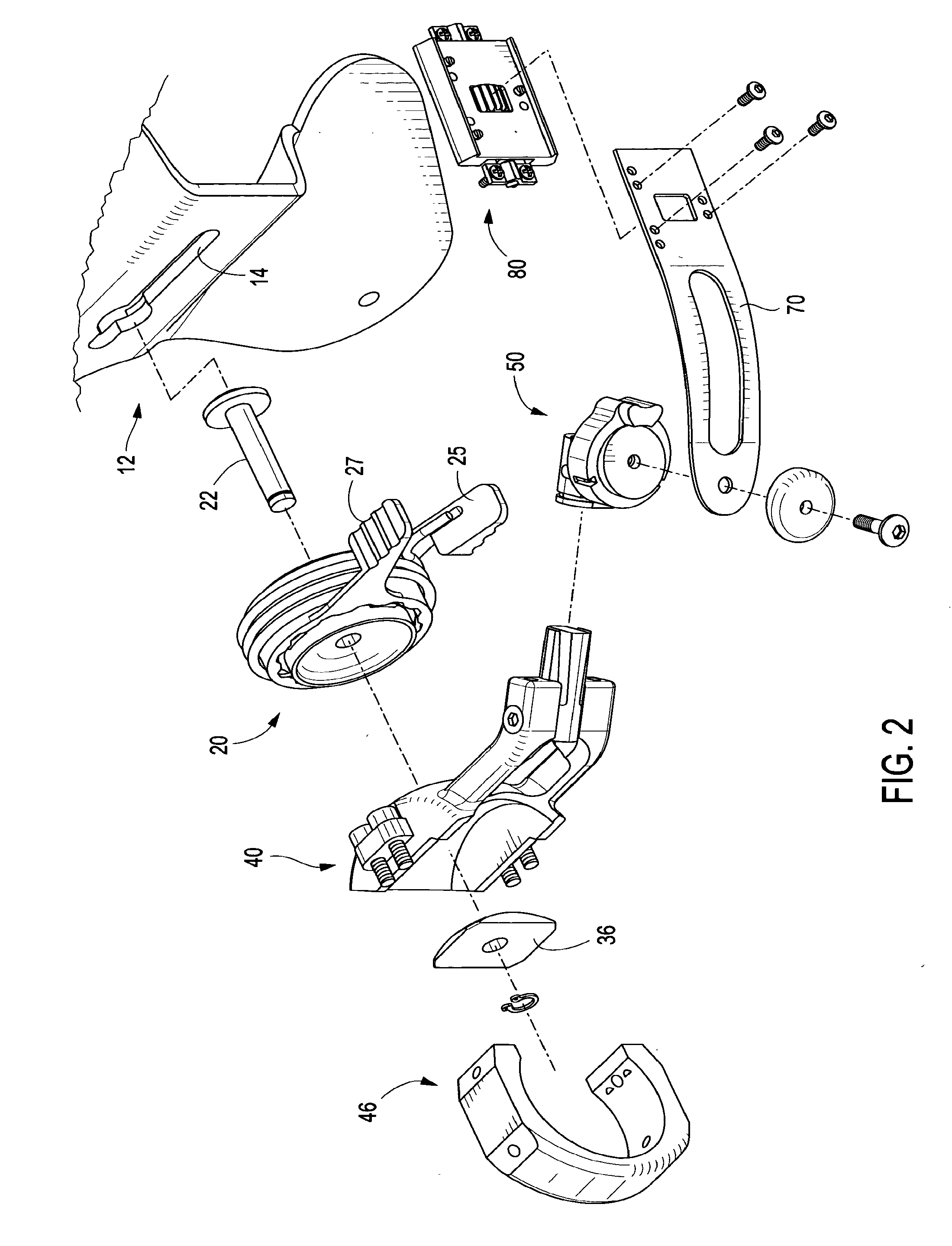
[0036] The invention will next be described with respect to exemplary embodiments shown in the figures. FIGS. 1 and 2 show an exemplary mounting system 10, which comprises several major components, each of which will be described in more detail below. These major components are head-mounted platform 12, shown in more detail in FIG. 3; friction base 20, shown in more detail in FIGS. 4 and 5; device cradle 40, shown in more detail in FIG. 6; indexing joint 50, shown in more detail in FIGS. 7-9B; inverting arm 70, shown in more detail in FIG. 10; and display slide assembly 80, shown in more detail in FIGS. 12-14.

[0037] Generally, head-mounted platform 12 provides a slot 14 and an insertion orifice 16 for mounting friction base 20. Slot 14 provides fore / aft translation of friction base 20 so the user may adjust eye relief. Friction base 20 is an expanding concave spherical nest that allows the user to adjust the position of the system. When opposing levers (thumb grips 25 and 27) are c...


PUM


Abstract

A mounting assembly for a vision enhancement device and associated vision enhancement display, the assembly comprising a display mounted to an arm positionable in front of the user's eye, a base member for receiving a cradle for the vision enhancement device and for attaching to a head-mounting platform, and one or more intermediate members for connecting the arm to the cradle. In one embodiment, the mounting system comprises one or more mechanisms for aligning the display optical axis with the vision enhancement device optical axis and with the user's line of sight, one or more mechanisms for orienting the vision enhancement device within multiple degrees of freedom without changing the alignment of the display optical axis with the device optical axis, and one or more mechanisms for toggling the display between an in-use position to at least one storage position, and, optionally, between right eye and left eye positions.

Description

FIELD OF THE INVENTION [0001] This invention relates to mounting / adjustment mechanisms for vision enhancement systems, particularly night vision systems, and more particularly video enhanced night vision systems. BACKGROUND OF THE INVENTION [0002] U.S. Pat. No. 6,560,029 to Dobbie et al., assigned to the common assignee of this invention, and incorporated herein by references, discloses a video enhanced night vision system comprising a head mount assembly, an image intensified video camera, and a display. Other pending applications, namely 10 / 024,436, published as U.S. Patent Application Publication No. U.S. 2003 / 0115661, and 10 / 024,650, published as U.S. Patent Application Publication No. U.S. 2003 / 0115662, both of which also name Dobbie et al. as inventors, are assigned to the common assignee of this invention, and are incorporated herein by reference. These applications disclose a head mount apparatus and adjustment mechanisms for a head mount apparatus, respectively, for use wit...

Claims


Application Information

Patent Timeline
IPC IPC(8): G02B7/02
CPCA42B3/042G02B2027/0138G02B27/0149
Inventor WILLEY, CHARLES D.BRILLHART, STEVEN A.DOBBIE, BLAIR R.
Owner ELBIT SYSTEMS OF AMERICA LLC
Why Eureka
Try Eureka