

Reactor with primary and secondary channels
a reactor and primary channel technology, applied in the field of catalytic reactors, can solve the problems of insufficient heat transfer from the center of the monolith to the reactor wall, insufficient mixing of fluids entering different primary channels, and insufficient heat transfer of prior ar
- Summary
- Abstract
- Description
- Claims
- Application Information
AI Technical Summary
Benefits of technology
Problems solved by technology
Method used
Image

Examples
example 1
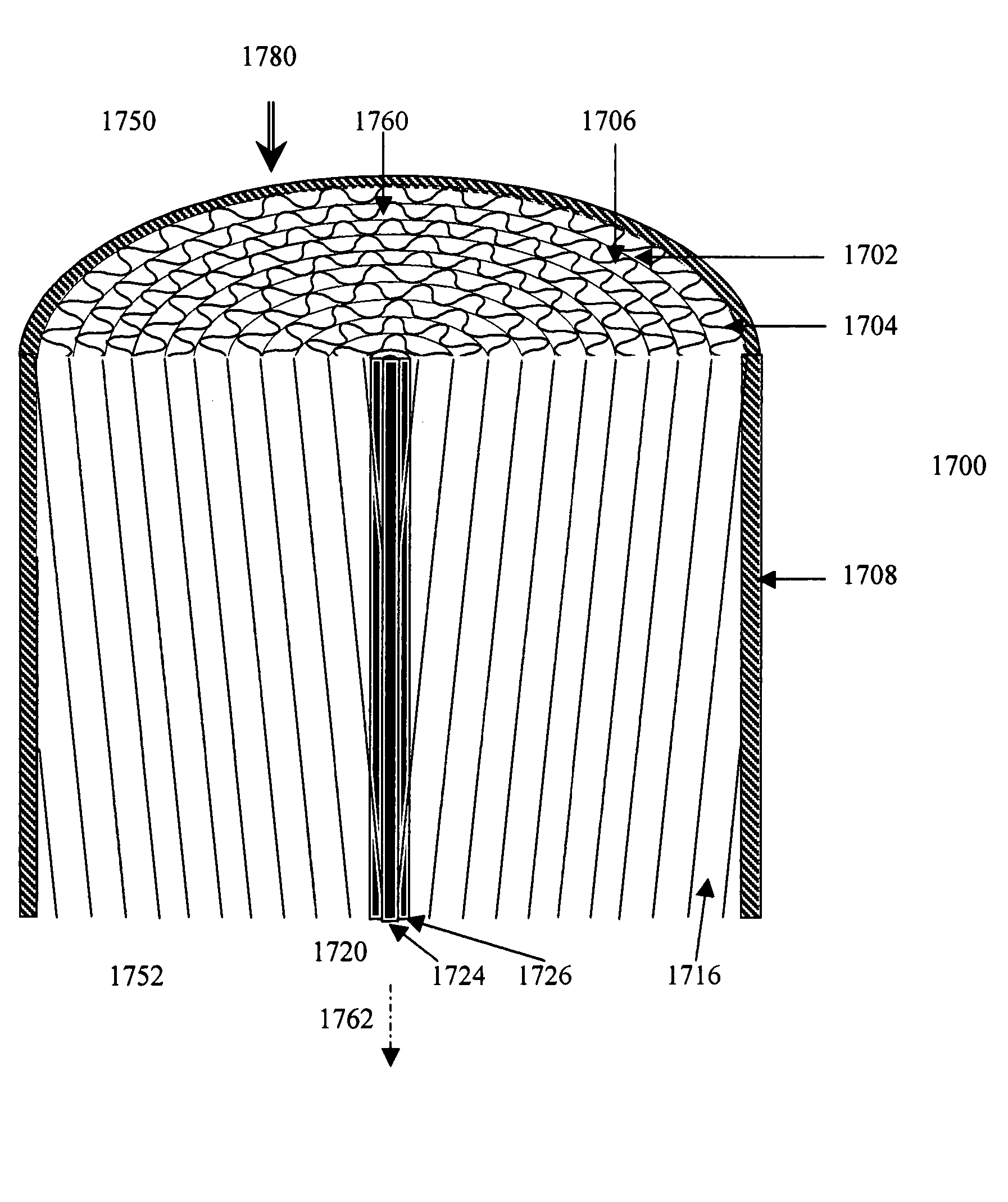
[0082] The example reactor comprises a steam reforming catalytic reactor comprising an upper monolith and a lower monolith. Each monolith is designed similarly to the monolith illustrated in FIG. 17, but without central column 1720 or spacers 1726. See Example 2 below for a more detailed description of the monolith in FIG. 17.
[0083] The monoliths are constructed of wire cloth. The wires are made of stainless steel or other material suitable for service in a steam reforming application. Pieces of wire cloth are corrugated with a sinusoidal pattern. Smooth and corrugated coated wire cloths are layered alternately and formed into frusta cones similar to those shown in FIG. 17 converging towards the reactor outlet. The smooth cones extend from their apexes to the reactor wall. The corrugated cones extend from the reactor wall to a distance of about 5 mm from the reactor axis and are trimmed to be flush with the reactor wall. The apexes of the cones point towards the exit of the reactor...
example 2
[0093]FIG. 17 illustrates longitudinal and transverse cross sections of a second example 1700 of the invention. The example is a catalytic converter and has an inlet 1750, an outlet 1752, a monolithic substrate 1760 and cylindrical reactor wall 1708. Monolithic substrate 1760 is constructed of alternating corrugated sheets 1704 and smooth sheets 1702. The alternating sheets may either be in the form of alternating smooth and corrugated nested cones or of interleaved smooth and corrugated helixes at an oblique angle to the reactor axis. The spaces between corrugations and smooth sheets define primary channels 1706.
[0094] The corrugated and smooth sheets are inclined at an oblique angle to converter axis 1762. Thus, at least one primary channel 1716 is blocked at one end by reactor wall 1708.
[0095] Example 1700 further comprises optional central column 1720. Central column 1720 comprises center rod 1724 and frusta-conical spacers 1726. The spacers interleave the smooth sheets to sup...
example 3
[0102]FIG. 18 illustrates transverse and longitudinal sections of alternate example reactor 1800. The reactor comprises an inlet 1850, outlet 1852, cylindrical reactor wall 1808 and monolith 1810. The monolith comprises alternating smooth sheets 1802 and corrugated sheets 1804. Portions of one each of the smooth and corrugated sheets are shown bold for clarity. The bold appearance does not form part of the invention. The layers of sheets are arranged radially and meet at or near a central core 1806. The spaces between the sheets are the primary channels.
[0103] A hollow conduit 1840 may be present in the center of the monolith. The hollow conduit will be discussed in more detail in the section “Additional Features” of the present application.
[0104] The primary channels are inclined at an angle with respect to the reactor walls such that at least some of the primary channels are blocked at one end and open at the other end. The angle of inclination between the primary channels and t...
PUM
| Property | Measurement | Unit |
|---|---|---|
| Fraction | aaaaa | aaaaa |
| Fraction | aaaaa | aaaaa |
| Pressure | aaaaa | aaaaa |
Abstract
Description
Claims
Application Information