Thermal treatment methods and apparatus with focused energy application

Inactive Publication Date: 2006-01-12
BOSTON SCI SCIMED INC +1
View PDF99 Cites 56 Cited by
  • Summary
  • Abstract
  • Description
  • Claims
  • Application Information

AI Technical Summary

Benefits of technology

[0024] Another aspect of the invention provides techniques of monitoring and controlling cardiac ablation procedures as discussed above. Still other aspects of the i

Problems solved by technology

This causes formation of a scar extending along the path where disruption occurred.
Such a scar can be created by conventional surgery, but this entails all of the risks and expense associated with cardiac surgery.
Tracing a precise path along the interior of a chamber in the heart of a living subject with the tip of a catheter involves inherent practical difficulties.
Although curved guide wires can be placed within the catheter so that the catheter tip will tend to follow the guide wire as the physician moves it, the process is still difficult.
Even with these structures, howev

Method used


Image

  • Thermal treatment methods and apparatus with focused energy application
  • Thermal treatment methods and apparatus with focused energy application
  • Thermal treatment methods and apparatus with focused energy application

Examples


Embodiment Construction

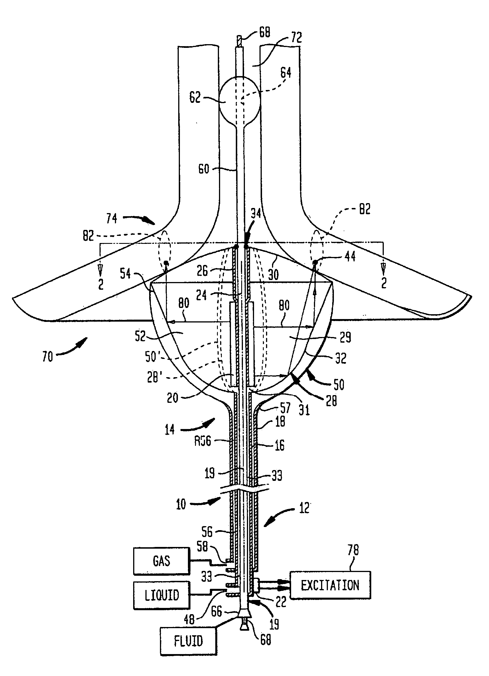
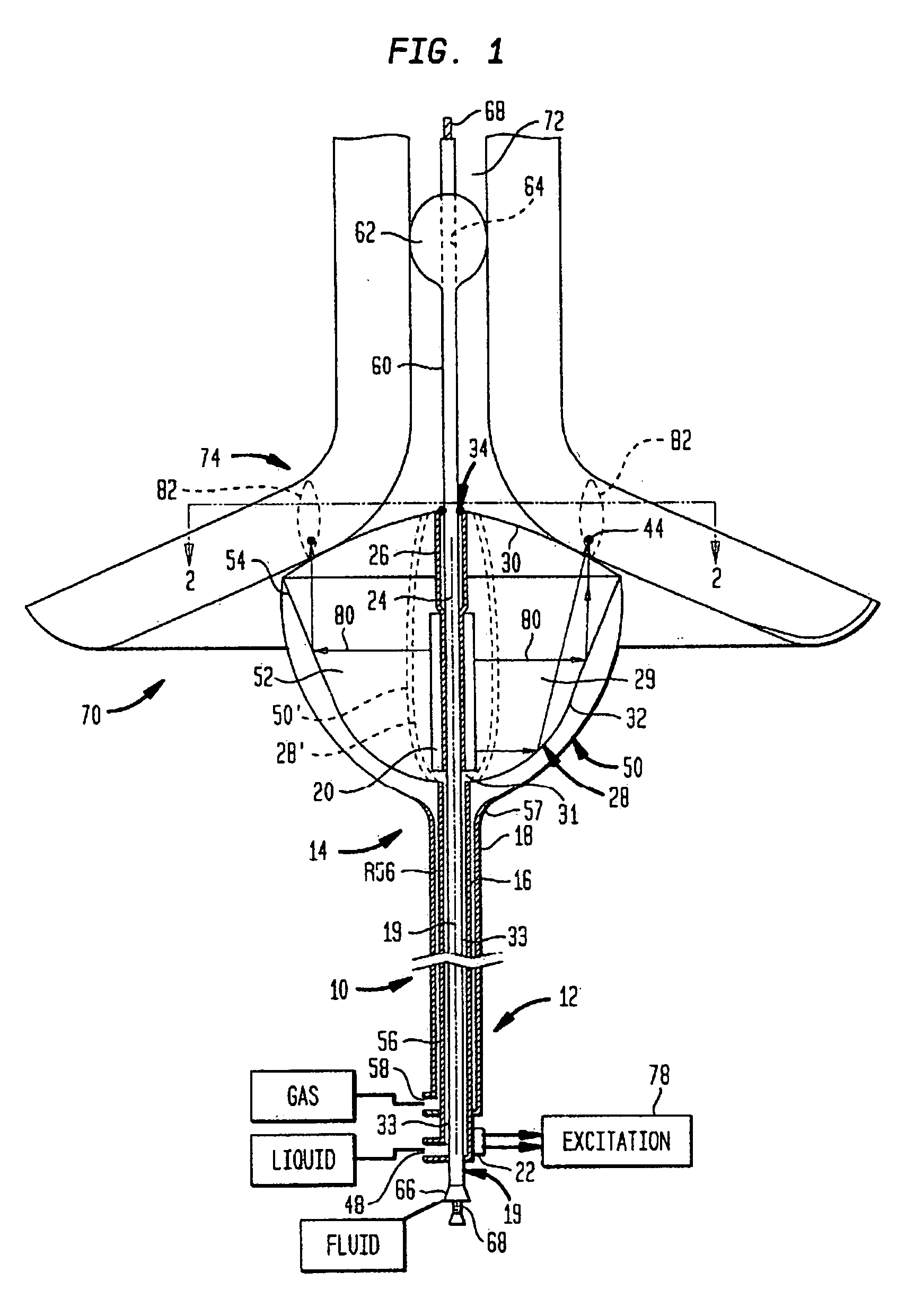
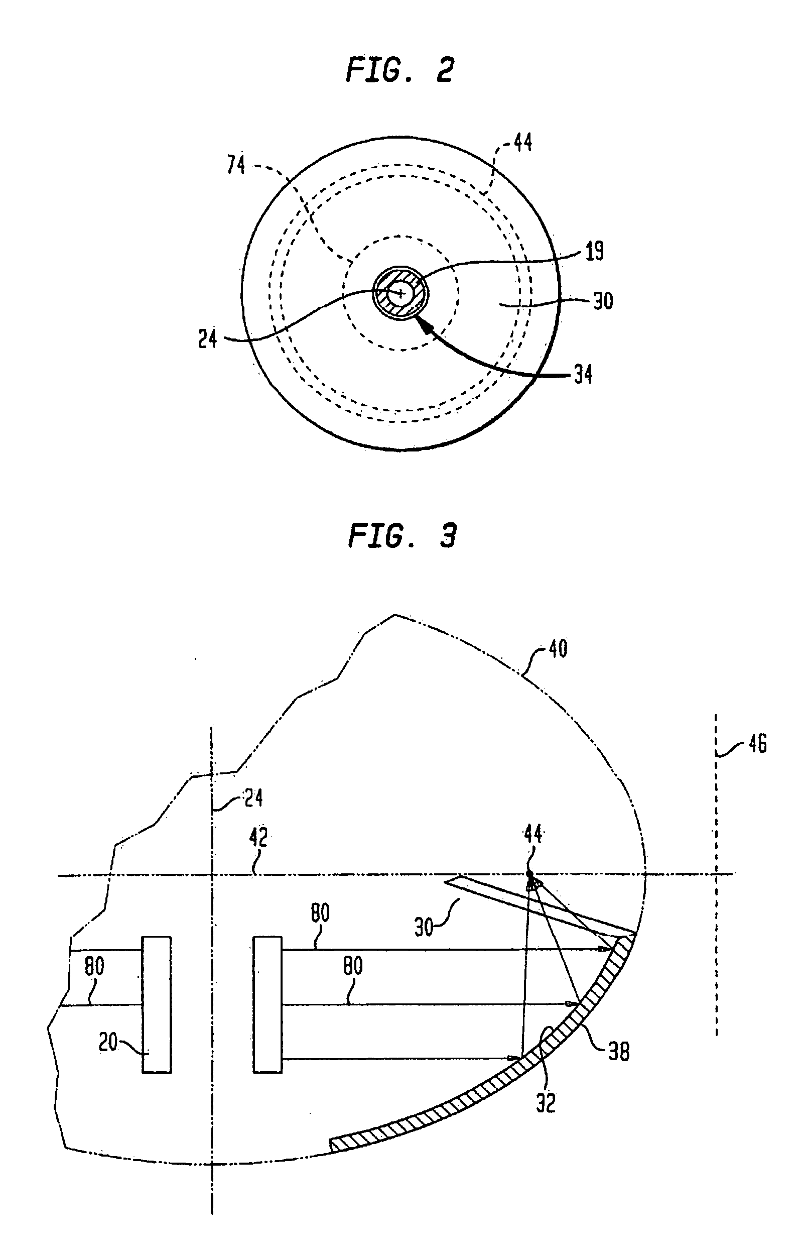
[0045] Apparatus according to one embodiment of the invention includes a probe structure 10 having a proximal end 12 and a distal end 14. A portion of the probe structure between the proximal and distal ends is omitted in FIG. 1 for clarity of illustration. The probe structure includes a tubular first catheter 16, a tubular second catheter 18 surrounding the first catheter and a tubular guide catheter 19 extending within the first catheter. The first catheter 16 carries a cylindrical ultrasonic transducer 20 adjacent its distal end. The cylindrical ultrasonic transducer may be a ceramic piezoelectric element such as lead titanate or a polymeric piezoelectric transducer such as PVDF-TRF (polyvinyledene fluoride-trifluoroethylene) copolymer transducer. A ceramic piezoelectric transducer typically is formed as a single hollow cylinder of ceramic piezoelectric material with thin metallic electrodes (not shown) disposed on its interior and exterior surfaces. A cylindrical polymeric piezo...


PUM


Abstract

A collapsible ultrasonic reflector incorporates a gas-filled reflector balloon, a liquid-filled structural balloon an ultrasonic transducer disposed within the structural balloon. Acoustic energy emitted by the transducer is reflected by a highly reflective interface between the balloons. In a cardiac ablation procedure, the ultrasonic energy is focused into an annular focal region to ablate cardiac tissue extending in an annular path along the wall. Devices for stabilizing the balloon structure and for facilitating collapse and withdrawal of the balloon structure are also disclosed.

Description

CROSS-REFERENCE TO RELATED APPLICATIONS [0001] The present application is a continuation of U.S. patent application Ser. No. 10 / 227,092, filed Aug. 23, 2002, which application is a divisional of U.S. patent application Ser. No. 09 / 905,227, filed Jul. 13, 2001, now U.S. Pat. No. 6,635,054, which claims benefit of the filing date of U.S. Provisional Patent Application Ser. No. 60 / 218,641, filed Jul. 13, 2000, the disclosures of which are incorporated by reference herein.FIELD OF THE INVENTION [0002] The present invention relates to medical procedures such as cardiac ablation and to devices and components useful in these and other uses. BACKGROUND OF THE INVENTION [0003] Contraction or “beating” of the heart is controlled by electrical impulses generated at nodes within the heart and transmitted along conductive pathways extending within the wall of the heart. Certain diseases of the heart known as cardiac arrhythmias involve abnormal generation or conduction of the electrical impulses...

Claims


Application Information

Patent Timeline
IPC IPC(8): A61B18/04A61B8/00A61B18/00A61B17/00A61B17/22A61B18/24A61F7/00A61F7/12A61M25/00A61N7/02
CPCA61B17/2202A61B17/2251A61B18/1492A61B18/24A61B2017/00274A61N7/022A61B2017/22027A61B2017/22068A61B2018/00214A61B2018/00547A61M2025/1059A61B2017/22024
Inventor FJIELD, TODDHARHEN, EDWARD PAULACKER, DAVID E.LOPATH, PATRICK DAVID
Owner BOSTON SCI SCIMED INC
Why Eureka
Try Eureka