Device for postoperative fixation back into the cranium of a plug of bone removed therefrom during a surgical operation
What is AI technical title?
AI technical title is built by Patsnap AI team. It summarizes the technical point description of the patent document.
a technology of cranial plug and surgical operation, which is applied in the field of devices for postoperative fixation back into the cranial plug of a surgical operation, can solve the problems of scalp infection, two halves not fused very well, and the contact between the plug and the rest of the cranial cavity is relatively unstable, so as to achieve stable mounting, easy and rapid manipulation, and save material
Inactive Publication Date: 2006-01-12
LERCH KARL DIETER
View PDF12 Cites 3 Cited by
Summary
Abstract
Description
Claims
Application Information
AI Technical Summary
This helps you quickly interpret patents by identifying the three key elements:
Problems solved by technology
Method used
Benefits of technology
Benefits of technology
[0004] With the aforesaid state of the art as a point of departure, the object of the present invention is a simpler and more rapid device for accurate and permanent postoperative fixation back into the cranium of a plug of bone removed therefrom during a surgical operation.
[0007] Titanium is particularly appropriate for the physiologically compatible metal. Such titanium alloys as Ti6A6Va are also appropriate. A device made of titanium is of advantage because it will not distort postoperative computerized-tomography images. The inner disk can be mounted more stable on the shaft of the pin if the transition between the head of the pin and the shaft is conical and dimensioned to ensure that a disk resting against the head will be forced tight around the shaft. Slits can also extend radially outward from the bore through the first disk to be mounted on the shaft. The center of the disk can be depressed. Areas can be removed from the disks at regular intervals between the bore and the edge to conserve material. The device can be applied to the two halves of bone by a procedure similar in principle to blind riveting. Notches can accordingly be introduced into each shaft to prevent the second disk mounted thereon from sliding away from the head of the pin. If the second disk on the shaft is deformed in a direction opposite that of its concavoconvexity, the deformation alone will secure it to the shaft by compression. The shaft can also be threaded and accommodate a nut. The nut can be tightened against the second disk. The second disk will in every case be displaced until its teeth engage the two halves of the joint, creating the desired fixation of the plug back into the rest of the cranium at the adjacent edges.
[0008] The novel device can be easily and rapidly manipulated and accomplishes the desired accurate and permanent postoperative fixation back into the cranium of a plug of bone removed therefrom during a surgical operation.
Problems solved by technology
The contact between the plug and the rest of the cranium is relatively unstable, however.
The two halves do not fuse together very well.
The scalp can also become inflamed.
Another drawback to such an approach is that the wire considerably distorts the images obtained in postoperative computerized tomography and accordingly impedes definitive interpretation of the soft structures of the brain.
Although using nonresorbable and physiologically compatible thread instead of wire does eliminate the last-mentioned drawback, the fixation of the plug to the rest of the skull is still unstable.
This approach, however, is also not very satisfactory.
It is both complicated and time-consuming and hence not inexpensive.
Method used
Image
Click on the blue label to locate the original text in one second.
Reading with bidirectional positioning of images and text.
Examples
Embodiment Construction
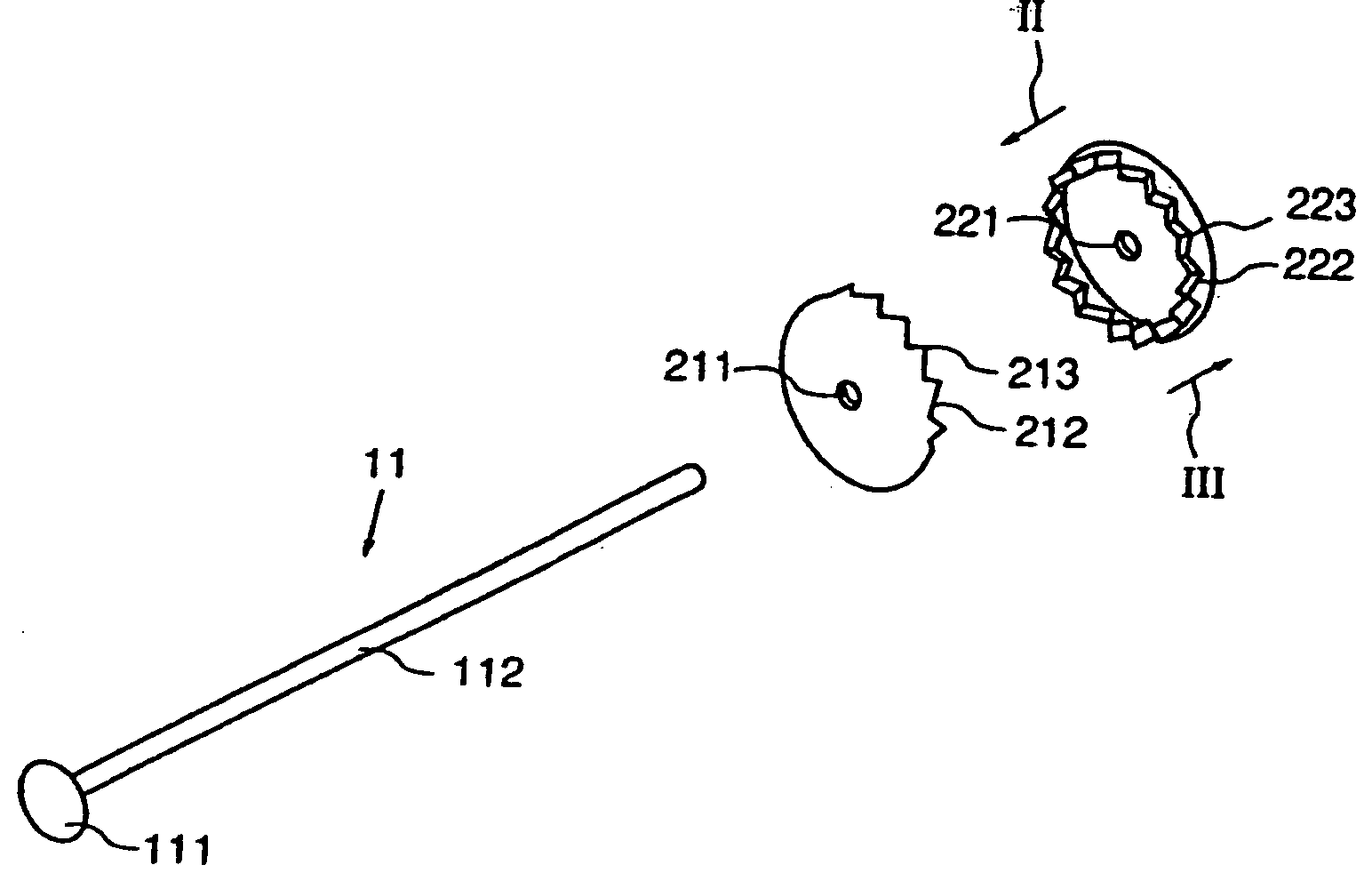
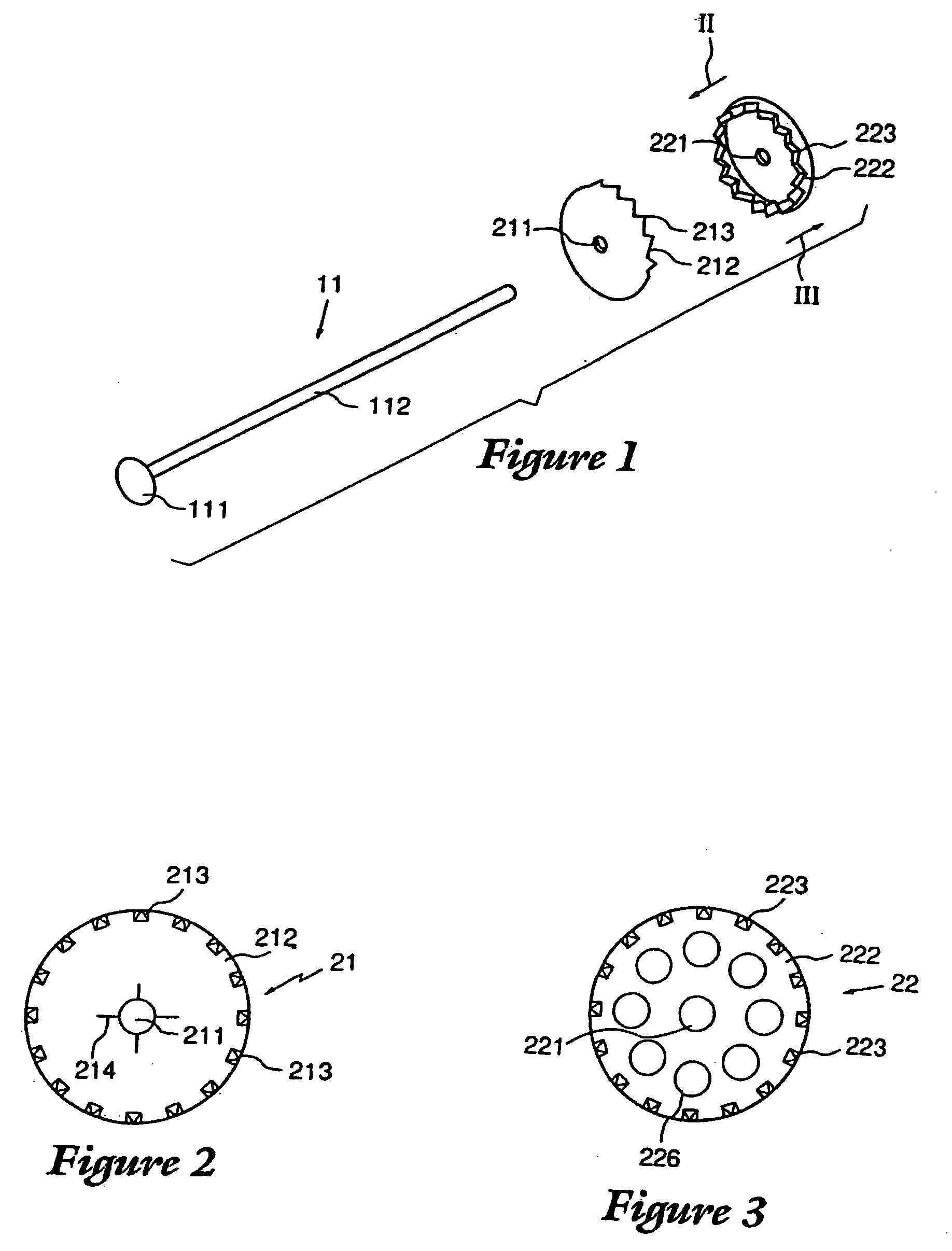
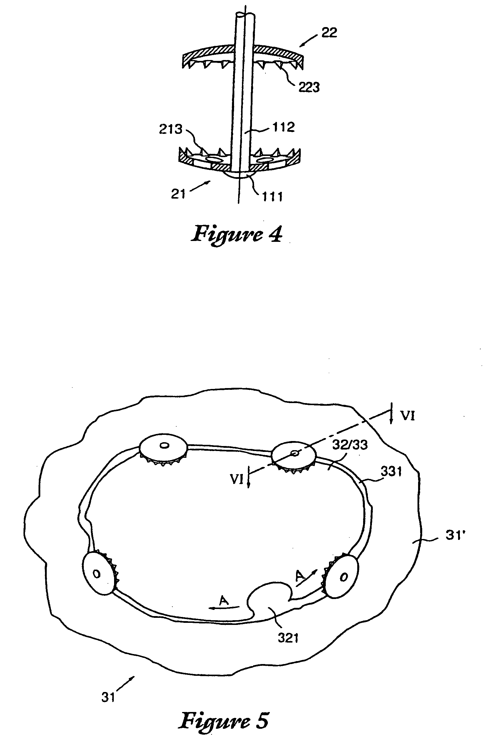
[0019] A device for postoperatively fixing back into the cranium a plug of bone removed therefrom during a surgical operation comprises a pin 11 and two concavoconvex disks 21 and 22. The pin comprises a shaft 112 and a head 111, Disk 21, the inner disk, is mounted on the shaft first and comes to rest against the inner surface of the plug and of the rest of the cranium that are to be united. Disk 22, the outer disk, is mounted on the shaft next and comes to rest against the outer surface of the plug and the rest of the cranium. There is a hole 211 through the center of each disk 21 and a hole 221 through the center of each disk 22. The shaft 112 of pin 11 extends through the holes 211 and 221 of the disks in the assembled device. A row of teeth 213 extends along the edge 212 of the concave side of disk 21, and a row of teeth 223 extends along the edge 222 of the concave side of disk 22. As will be evident from FIGS. 1 and 4, disks 21 and 22 are mounted on the shaft 112 of pin 11 wit...
PUM
Abstract
A device for rapid reattachment of a bone flap to a cranium after a surgical operation is provided. The device comprises a pin comprising an elongated shaft, an inner disk and an outer disk. At least the outer disk comprises a central bore. The pin and inner disk are adapted to be assembled together to form a pin and inner disk assembly such that the inner disk is located at one end of the pin. The outer disk is adapted to be mounted on the shaft of the pin with the shaft of the pin extending through the central bore of the outer disk. The device is operated by (i) positioning the inner disk on the inside of the cranium with the shaft of the pin extending through the kerf between the bone flap and the cranium, (ii) forcing the outer disk downwardly on the shaft of the pin toward the inner disk until the outer disk securely engages the outside of the bone flap and the cranium, such that the bone flap is securely held in place between the inner disk and the outer disk, and (iii) trimming off an excess portion of the shaft extending out beyond the outer disk.
Description
[0001] This application is a continuation of U.S. patent application Ser. No. 10 / 793,814, filed Mar. 8, 2004, which is a continuation of prior U.S. patent application Ser. No. 10 / 011,379, filed Oct. 22, 2001, now U.S. Pat. No. 6,726,688, which is a continuation of prior U.S. patent application Ser. No. 09 / 827,861, filed Apr. 6, 2001, now U.S. Pat. No. 6,328,743 B2, which is a continuation of prior U.S. patent application Ser. No. 09 / 494,599, filed Jan. 31, 2000, now U.S. Pat. No. 6,270,500 B1, which is a continuation of U.S. patent application Ser. No. 09 / 088,175, filed Jun. 1, 1998, now U.S. Pat. No. 6,068,631, which is a continuation of U.S. patent application Ser. No. 08 / 790,071, filed Jan. 28, 1997, now U.S. Pat. No. 5,800,436.BACKGROUND OF THE INVENTION [0002] The present background of the invention concerns a device for postoperative fixation back into the cranium of a plug of bone removed therefrom during a surgical operation. [0003] It is often necessary during brain surgery...
Claims
Application Information
Patent Timeline
Application Date:The date an application was filed.
Publication Date:The date a patent or application was officially published.
First Publication Date:The earliest publication date of a patent with the same application number.
Issue Date:Publication date of the patent grant document.
PCT Entry Date:The Entry date of PCT National Phase.
Estimated Expiry Date:The statutory expiry date of a patent right according to the Patent Law, and it is the longest term of protection that the patent right can achieve without the termination of the patent right due to other reasons(Term extension factor has been taken into account ).
Invalid Date:Actual expiry date is based on effective date or publication date of legal transaction data of invalid patent.
Patent Type & AuthorityApplications(United States)

