System and method for aligning multiple sighting devices

a technology of sighting device and alignment method, which is applied in the direction of distance measurement, angle measurement, instruments, etc., can solve the problems of limiting the range of applicability of taniguchi system, limiting the movement of users, and preventing certain spontaneous operations

Active Publication Date: 2006-01-19
SR2 GROUP
View PDF17 Cites 23 Cited by
  • Summary
  • Abstract
  • Description
  • Claims
  • Application Information

AI Technical Summary

Problems solved by technology

This latter method, however, requires an initial coordinate alignment step to synchronize the two devices, which may preclude certain spontaneous operations.
While the visual feedback provided to the second operator directing her towards the location of the target ameliorates verbal direction commands such as those discussed above, several deficiencies of the Taniguchi system limit its range of applicability.
It should be apparent to the skilled observer that such a system severely restricts the movement of its users.
However, rotational encoders are not the only means by which absolute bearing may be determined.
Rotational accelerometers are also capable of providing an absolute bearing, but are subject to drift.
Neither of these devices can provide consistent reliable accuracy for aligning optical systems having magnification.
While duplicating, or even translating, the movement of one device through pointing movements of another device is both well-known and useful, the technique can be limiting in other sighting applications.
Even then, a user may wish to ignore the sightings of other users and continue aiming his own equipment independently, a option that would not be possible in systems practicing the mechanical slaving techniques of the prior art.

Method used


Image

  • System and method for aligning multiple sighting devices
  • System and method for aligning multiple sighting devices
  • System and method for aligning multiple sighting devices

Examples


Embodiment Construction

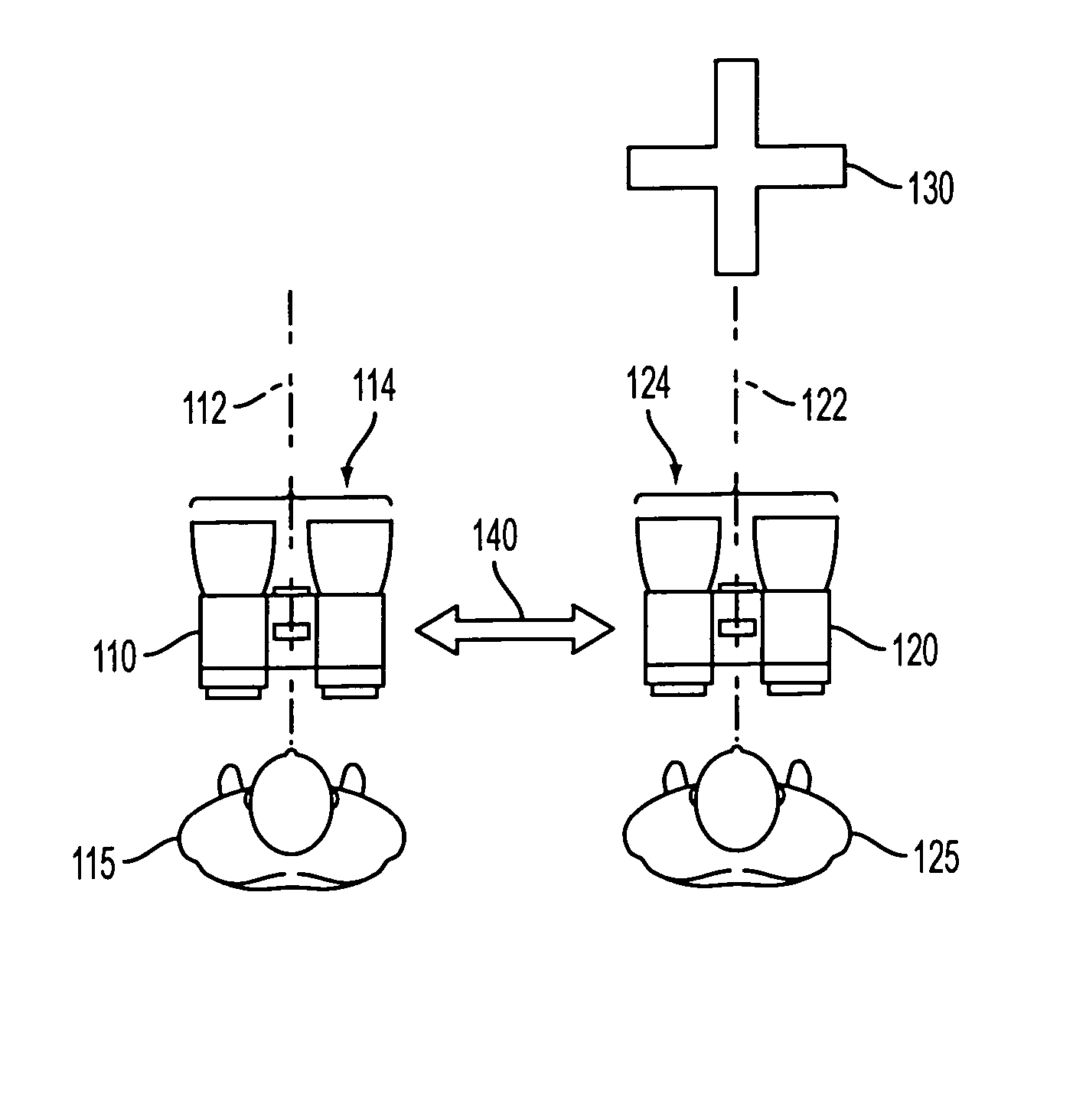
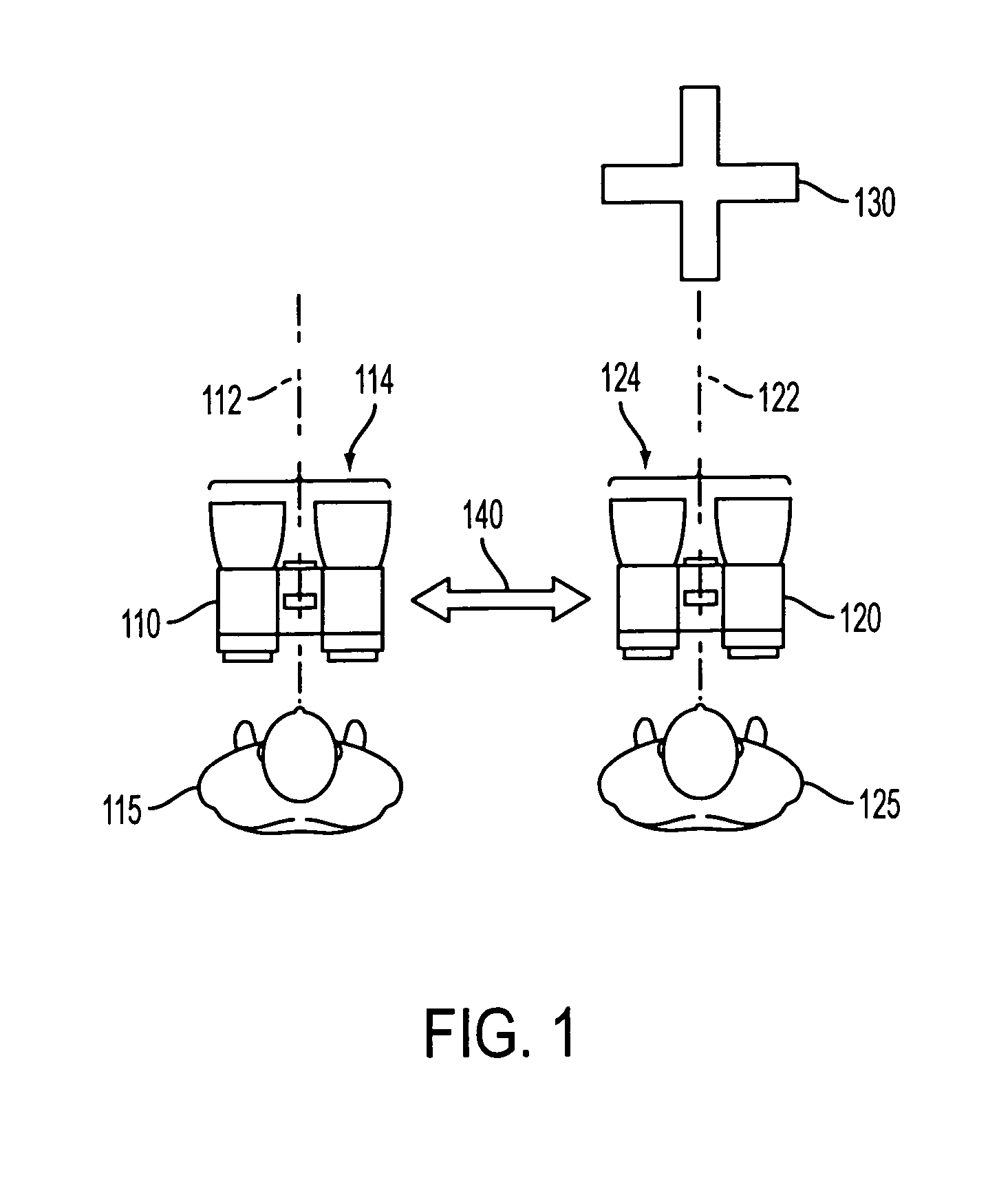
[0034] For purposes of explanation of the inventive concept, a basic configuration of fundamental components of the present invention is broadly illustrated in FIG. 1. As is shown in the Figure, two sighting devices, 110 and 120 are in use by two separate users 115 and 125, respectively. Whereas, the sighting devices are illustrated schematically in the Figure as optical sighting devices, particularly binoculars, any sighting device may be substituted for either or both of 110 or 120 with no material change in the operation of the invention. Moreover, the sighting devices need not be configured for operation at optical wavelengths; the term “sighting device” as used herein will refer to a directive device in which a primary receiving aperture, such as is generally shown at 114 and 124 of FIG. 1, is to be pointed or aimed at a target object. The exemplary embodiments, for purposes of description, will be optical sighting devices such as binoculars, telescopes, spotting scopes, rifle ...


PUM


Abstract

A system of independently oriented sighting devices includes a first sighting device (120) and a second sighting device (110). Upon aligning a line of sight of the first sighting device (12) with a target object (130), the first sighting device transmits a reference signal over a communications link (140). The second sighting device (110) determines its orientation in space relative to the orientation of the first sighting device (120) from characteristics of the reference signal. Thus, absolute coordinates of the target object (130) need not be known by the second sighting device (110) nor is it required that they be transmitted by the first sighting device (120). The user (115) of the second sighting device is directed to rotate the second sighting device (110) towards the target object (130) via feedback through guidance indicators located in a viewing port (250) thereof.

Description

RELATED APPLICATION INFORMATION [0001] This Application is based on U.S. Provisional Patent Application Ser. No. 60 / 571,913, filed on 17 May 2004.BACKGROUND OF THE INVENTION [0002] 1. Field of the Invention [0003] The present invention most directly relates to alignment of two or more directional devices, and more particularly, to alignment of sighting devices. The invention further relates specifically to dynamically aligning sighting devices to allow two or more users to easily locate a common target object through independently translated viewing ports. [0004] 2. Description of the Prior Art [0005] Sighting devices, particularly optical sighting devices, are used in many applications and are varied in configuration. Common optical sighting devices include, but are by no means limited to, binoculars, telescopes, rifle and other weapon sights, and surveying equipment. A user might sight through an optical device, generally, to (a) magnify or otherwise improve viewing of a target in...

Claims


Application Information

Patent Timeline
Patent Type & Authority Applications(United States)
IPC IPC(8): G01C1/00
CPCG02B23/00G01C3/04
Inventor SIERACKI, JEFFREY M.SILVER, CRAIG L.
Owner SR2 GROUP
Why Eureka
Try Eureka