
User-based signal indicator for telecommunications device and method of remotely notifying a user of an incoming communications signal incorporating the same

a technology of a user-based signal and a telecommunications device, which is applied in the field of personal communication devices, can solve the problems of inability to notify users of incoming calls, inability to hear the ring of the cellular phone, and inability to see the cellular phon

Inactive Publication Date: 2006-10-31
WILLIAMS DANIEL P
View PDF54 Cites 354 Cited by
  • Summary
  • Abstract
  • Description
  • Claims
  • Application Information

AI Technical Summary

Benefits of technology

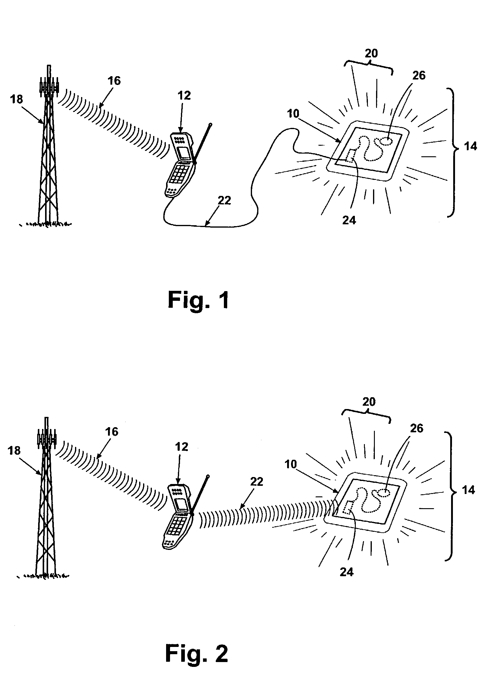
[0010]The present invention provides a remote notification device that alerts a user of a personal communication device such as a cellular phone or pager of an incoming call, message, or page in situations where the user is neither in sight of, able to hear, nor in physical contact with their personal communication device, without altering the user's desired appearance.

Problems solved by technology

These women often cannot see their cellular phone because it is contained within an opaque purse.
Nor can these women hear their cellular phone ring, due to ambient noise from such sources as music and other patrons.
And these women are obviously not in physical contact with their cellular phones while those phones are in their purses, hence the vibrate option on their cellular phone is incapable of notifying them of the incoming call.
As a result of this decision to place their cellular phone in their purses, many women miss many incoming calls.
This causes inconvenience, disruption to social lives, and has the potential to render these women unreachable in important and emergency situations.
While these devices do free their users from having to be within sight, able to hear, or in physical contact with their cellular phones, they do not meet the needs that are met by the present invention.

Method used


Image

  • User-based signal indicator for telecommunications device and method of remotely notifying a user of an incoming communications signal incorporating the same
  • User-based signal indicator for telecommunications device and method of remotely notifying a user of an incoming communications signal incorporating the same
  • User-based signal indicator for telecommunications device and method of remotely notifying a user of an incoming communications signal incorporating the same

Examples


first embodiment

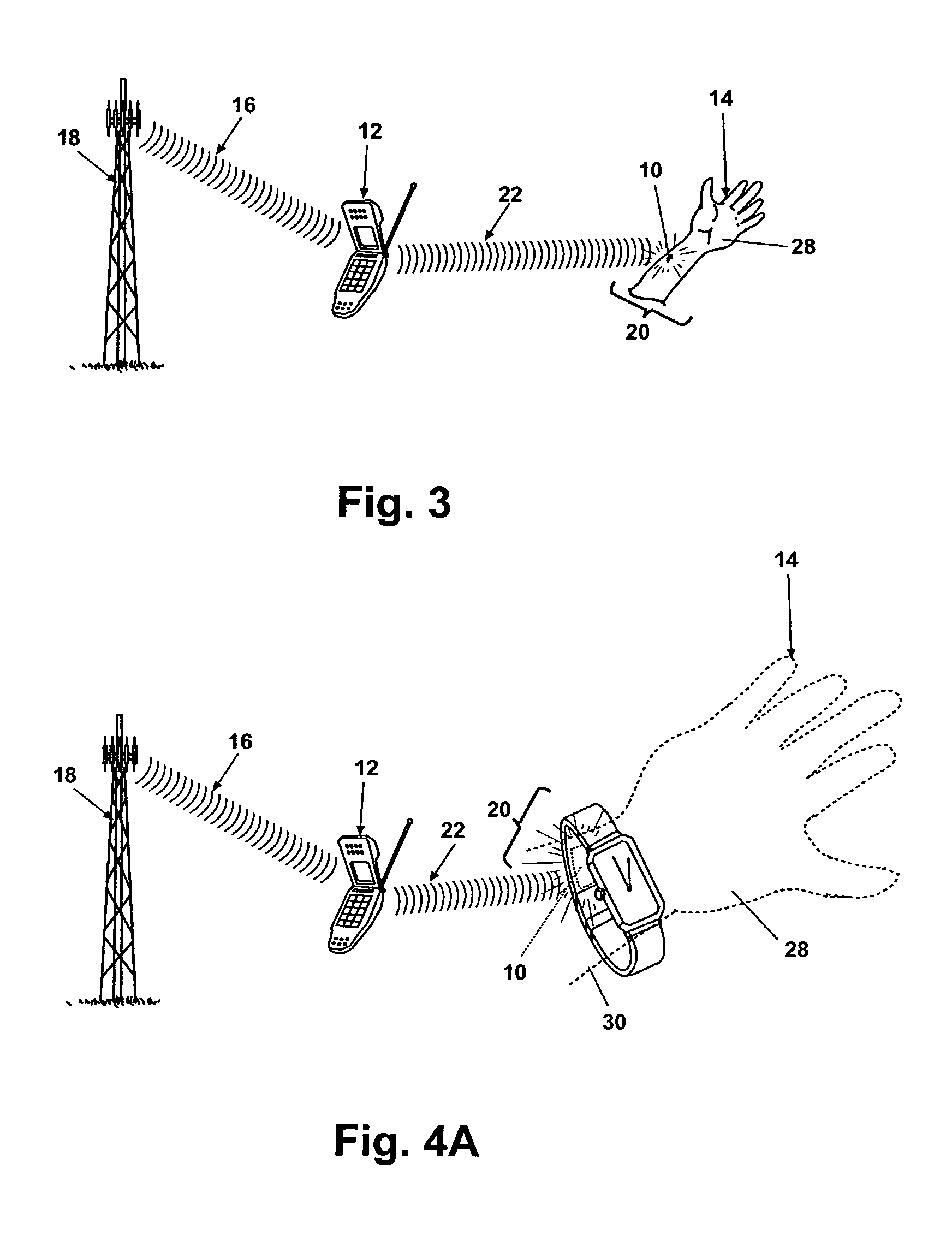
[0049]the association of the remote notification device 10 with the user 14 is shown in FIG. 3 wherein the remote notification device is mounted to the user's skin and wherein the remote notification device 10 is associated with the telecommunications device 12 by a wireless link 22. The example association shown in FIG. 3 is a dermal patch removably mounted on the user's skin (e.g., a user's hand 28) in which the remote notification device 10 is embedded. The dermal patch containing the remote notification device 10 can be provided with an aesthetically-pleasing color, such as a skin tone color, or, alternatively, worn on the user's skin in an area typically concealed by clothing. In addition, the dermal patch can have a separate adhesive portion which can alternatively be disposable so that the dermal patch can be reused upon expiry of the adhesive portion.

second embodiment

[0050]the association of the remote notification device 10 with the user 14 is shown in FIG. 4A wherein the remote notification device 10 is mounted to a bodily-worn accessory such as a watch, bracelet or anklet and wherein the remote notification device 10 is associated with the telecommunications device by a wireless link 22. The bodily-worn accessory shown in FIG. 4A is a watch which has the remote notification device 10 associated therewith, but it would be apparent to one skilled in the art that an anklet or bracelet could be substituted for the watch shown in FIG. 4A without departing from the scope of this invention.

[0051]FIG. 4B shows the second embodiment association of the remote notification device 10 with a bodily-worn accessory of a user 14 the specific embodiment of the bodily-worn accessory in FIG. 4B is a ring worn on a finger 32 of the user 14.

[0052]FIG. 4C shows the second embodiment association of the remote notification device 10 with a bodily-worn accessory of a...

third embodiment

[0054]the association of the remote notification device 10 with the user 14 is shown in FIG. 5A wherein the remote notification device 10 is mounted to bodily-worn clothing such as a clip that attaches to a collar of a shirt and / or a blouse 38 of the user 14 wherein the remote notification device is associated with the telecommunications device by a wireless link 22. It will be understood that the remote notification device 10 can be embedded and / or sewed within the clothing 38 or fastened thereto by a clip, snap; button, hook-and-loop fastener attachment (e.g., VELCRO®) or other means which would be apparent to one skilled in the art. In addition, the clothing 38, while shown by example as a shirt and / or blouse 38, can comprise any bodily-worn accessory such as a pair of pants, socks, T-shirt, underwear, coat, suit, sport coat, jacket and the like.

[0055]FIG. 5B shows the third embodiment association of the remote notification device 10 with a bodily-worn clothing 38 of a user 14 w...


PUM


Abstract

The present invention provides a remote notification device in electronic communication with a user's personal communication device that alerts the user that the personal communication device is receiving an incoming telecommunications signal. A user who is not in operable contact with the communication device is alerted to the incoming call, message, or page by the remote notification device, which is in operable contact with the user, and alerts the user with a suitable indication (e.g., visual, audible, and / or tactile). The remote notification device preferably permits the user to not alter his or her desired appearance in social situations. The remote notification device is easily concealable or integral to an article of clothing, piece of jewelry, piercing, or accessory that the user desires to wear or carry independent of the desire to be notified of incoming calls, messages, or pages.

Description

BACKGROUND OF INVENTION[0001]1. Field of the Invention[0002]The present invention relates to the field of personal communication devices such as cellular phones and pagers, and in particular to the field of remote notification devices that alert users of personal communication devices of incoming calls, messages, or pages.[0003]2. Description of the Related Art[0004]Modern personal communication devices, such as cellular phones and pagers, typically alert users of an incoming call, message, or page with some sort of signal. These signals generally take the form of an audible ring, a vibration, a visual signal such as a light, or some combination of the foregoing. These signals typically originate from the cellular phone or pager itself. In most social situations, this type of notification is adequate, as the user is within sight of, able to hear, or in physical contact with their cellular phone or pager.[0005]The balance of this statement of the problem will be stated in terms of an...

Claims


Application Information

Patent Timeline
IPC IPC(8): H04B1/38H04M1/00
CPCH04M1/7253H04M19/04H04M1/72412
Inventor WILLIAMS, DANIEL P.
Owner WILLIAMS DANIEL P
Learn More