Coiled tubing conveyed milling

a technology of conveyed milling and coiled tubing, which is applied in the direction of drinking water installation, borehole/well accessories, construction, etc., can solve the problems of erratic milling, coiled tubing is considerably weaker than rigid tubing, and the associated cost is fair, so as to maintain the weight

Active Publication Date: 2006-01-19
BAKER HUGHES INC
View PDF26 Cites 21 Cited by
  • Summary
  • Abstract
  • Description
  • Claims
  • Application Information

AI Technical Summary

Benefits of technology

[0007] Milling in casing that is over 4½ inches is done with coiled tubing that is anchored against torque reaction. An improved debris catcher is part of the bottom hole assembly to capture cuttings from the milling. A thruster can be used to maintain weight on the mill during the milling. The coiled tubing supports a mud motor to drive the mill. Return fluid is separated from the cuttings and returned to the surface.

Problems solved by technology

There is a fair amount of expense associated with erecting the rig on site and handling the tubing to assembly and disassemble the string for trips into the well.
However, the use of coiled tubing creates other issues that are not of concern when using rigid tubing.
The main problem is that coiled tubing is considerably weaker than rigid tubing.
If the torque reaction turns the coiled tubing it can raise the mill off the packer being milled or bounce it, resulting in erratic milling.
Worse still, the coiled tubing can fail from being over-torqued.
For this reason milling with coiled tubing was limited in the past to very small applications, generally with casing sizes fewer than four inches.
The milling process generates debris in the wellbore.
Some debris catchers can be run in the same trip as the milling equipment but due to the way such tools operate they can't have a mud motor below them.

Method used


Image

  • Coiled tubing conveyed milling
  • Coiled tubing conveyed milling
  • Coiled tubing conveyed milling

Examples


Embodiment Construction

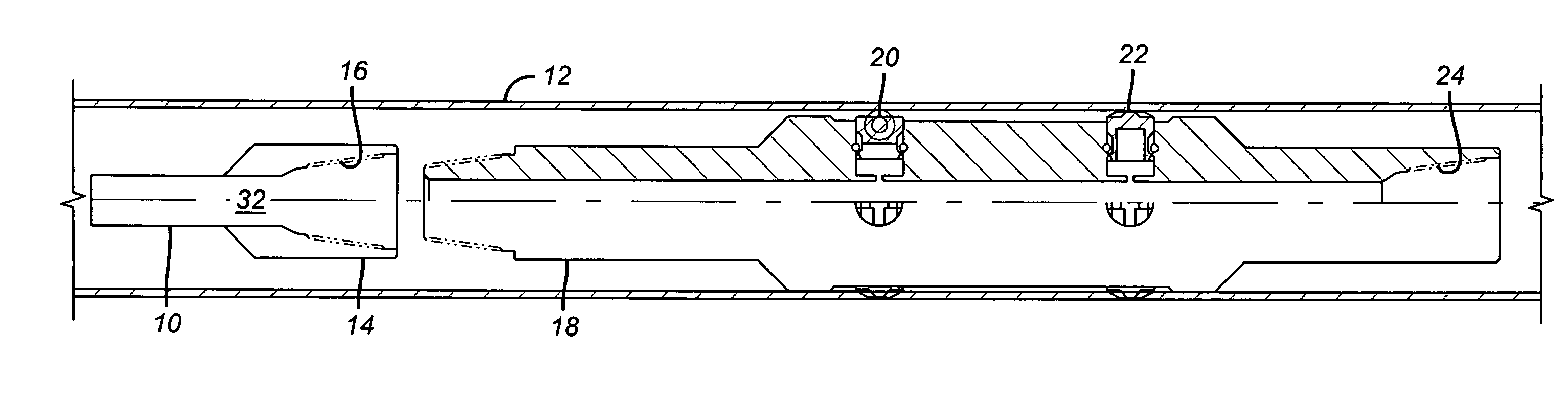
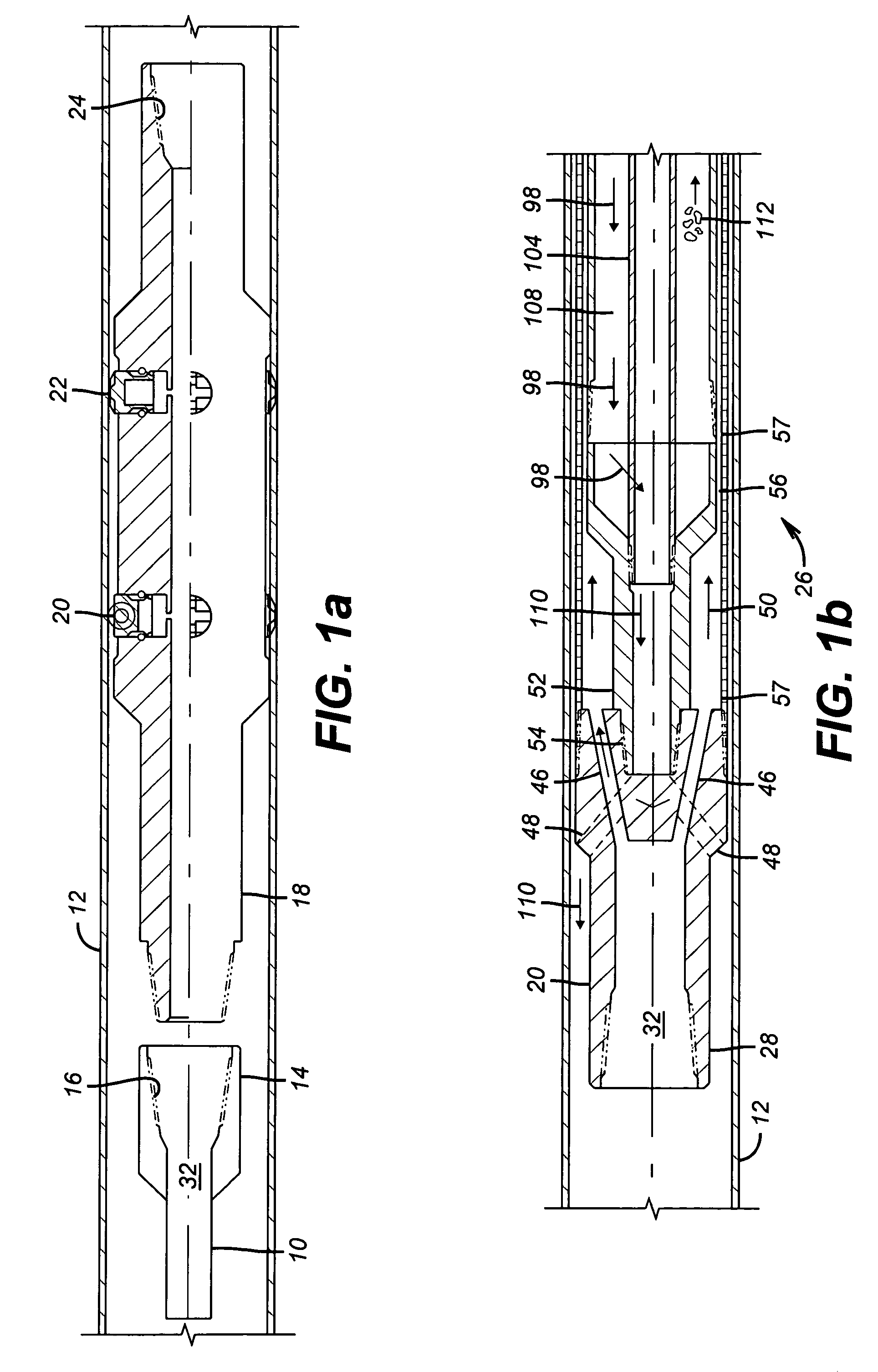
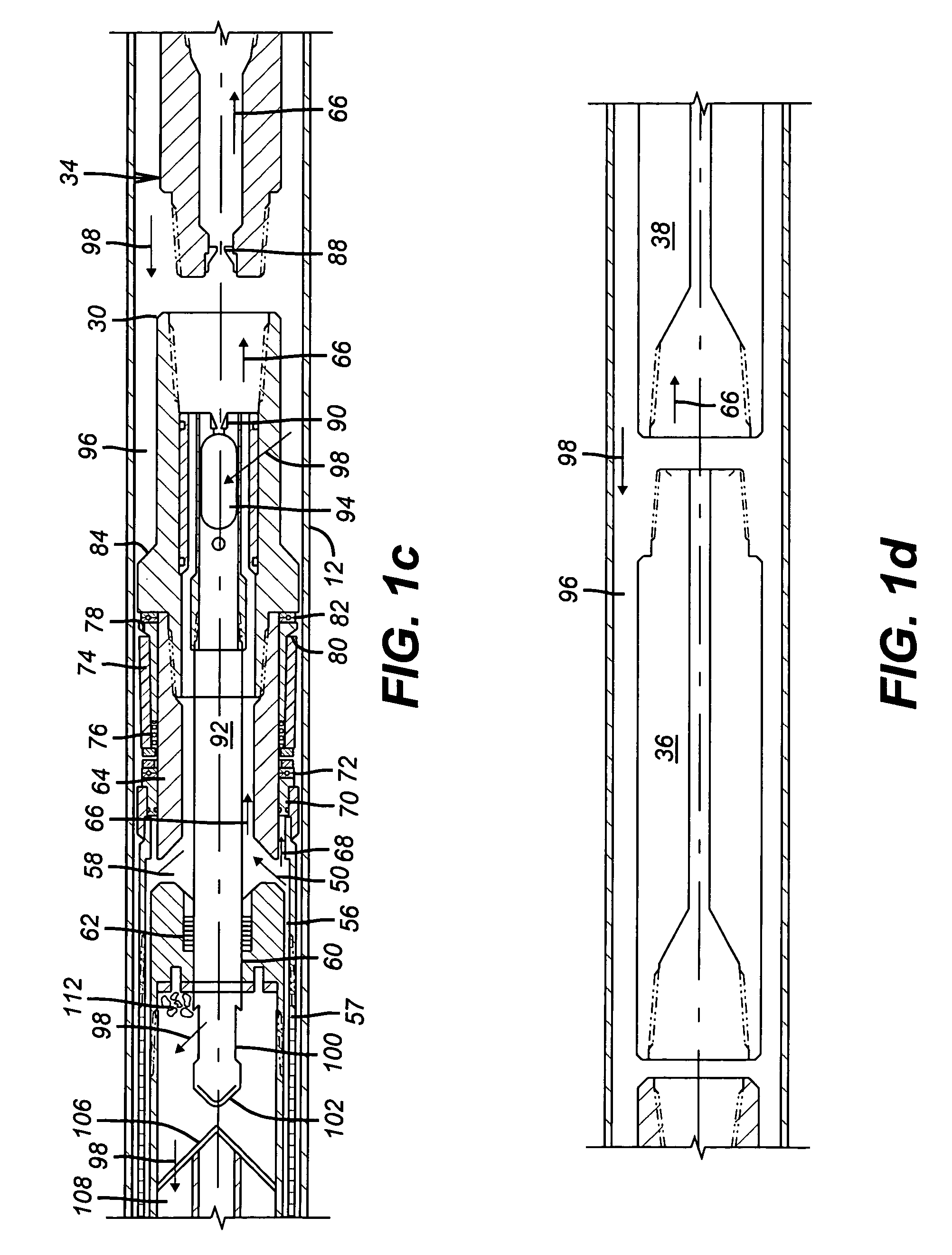
[0009] Referring to FIG. 1a, coiled tubing 10 is run into casing 12. At the lower end 14 is a threaded connection 16 to which an anchor 18 is attached. The anchor 18 is preferably of a known design as described in U.S. Pat. No. 6,276,452. It features extending gripping members 20 and 22 that are hydraulically actuated by fluid circulation down the coiled tubing 10. A connection 24 is at the lower end of the anchor 18 to attach the debris catcher 26. The debris catcher 26 runs from upper end 28 to lower end 30 in FIG. 1c. Continuing with the preferred assembly, a jet sub 34 is connected to lower end 30. A mud motor 36 (shown schematically) is connected to jet sub 34. A thruster 38 (shown schematically) is connected to mud motor 36. A mill 40 is connected to the thruster 38. Mill 40 comes in contact with the object 42 (shown schematically) to be milled in the wellbore. That object 42 could be a packer, a bridge plug, another downhole tool, or a section of casing or tubular. Depending ...


PUM


Abstract

Milling in casing that is over 4½ inches is done with coiled tubing that is anchored against torque reaction. An improved debris catcher is part of the bottom hole assembly to capture cuttings from the milling. A thruster can be used to maintain weight on the mill during the milling. The coiled tubing supports a mud motor to drive the mill. Return fluid is separated from the cuttings and returned to the surface.

Description

PRIORITY INFORMATION [0001] This application claims the benefit of U.S. Provisional Application No. 60 / 589,053, filed on Jul. 19, 2004.FIELD OF THE INVENTION [0002] The field of the invention related to milling downhole with a bottom hole assembly delivered on coiled tubing with provisions to absorb torque reaction from milling and to collect generated debris near the milling location. BACKGROUND OF THE INVENTION [0003] Workovers in existing wells can require removal of packers or plugs by milling them out. Other occasions can also occur where there is a need to mill out a tool or even a casing section. If the well is not too deviated, rigid tubing has been used to support a mill and the rotation force provided from surface equipment. Alternatively, where the deviated nature of the wellbore precludes rotation form the surface, the bottom hole assembly includes a mud motor to turn the mill. The bottom hole assembly is still delivered on rigid tubing but such tubing above the mud moto...

Claims


Application Information

Patent Timeline
Patent Type & Authority Applications(United States)
IPC IPC(8): E21B43/11E21B31/08
CPCE21B29/00E21B27/005
Inventor LYNDE, GERALD D.DAVIS, JOHN P.
Owner BAKER HUGHES INC
Why Eureka
Try Eureka