
Lightweight High-Performance Pipelayer

Active Publication Date: 2011-04-14
CATERPILLAR INC
View PDF21 Cites 11 Cited by
  • Summary
  • Abstract
  • Description
  • Claims
  • Application Information

AI Technical Summary

Benefits of technology

[0015]In accordance with a still further aspect of the disclosure, in a pipelayer having an undercarriage, chassis and boom weight of A and a machine maximum lifting capacity of B, a heavy lift attachment is disclosed which is adapted to increase the machine maximum lifting capacity to a value greater than B within a heavy lift operating range while maintaining the machine weight as A.

Problems solved by technology

However, the installation of such pipelines is often very challenging.
The locations of such oil and gas wells are commonly some of the most remote areas on earth, and the terrain over which the pipeline must traverse is often some of the most rugged.
The land may have significant elevational changes, and be subject to mudslides, severe weather, deep forestation and the like.
This can result in a very long length of conduit (sometimes exceeding a mile) which must be laid into the ground in coordinated fashion.
This right-of-way is ideally flat and sufficiently wide to easily accommodate the pipelayer but given the constraints imposed by the area topography and space availabilities of the local region or country, this may not always be the case.
Pipelayers therefore often need to carry not only very heavy loads, but do so without being on level, stable ground.
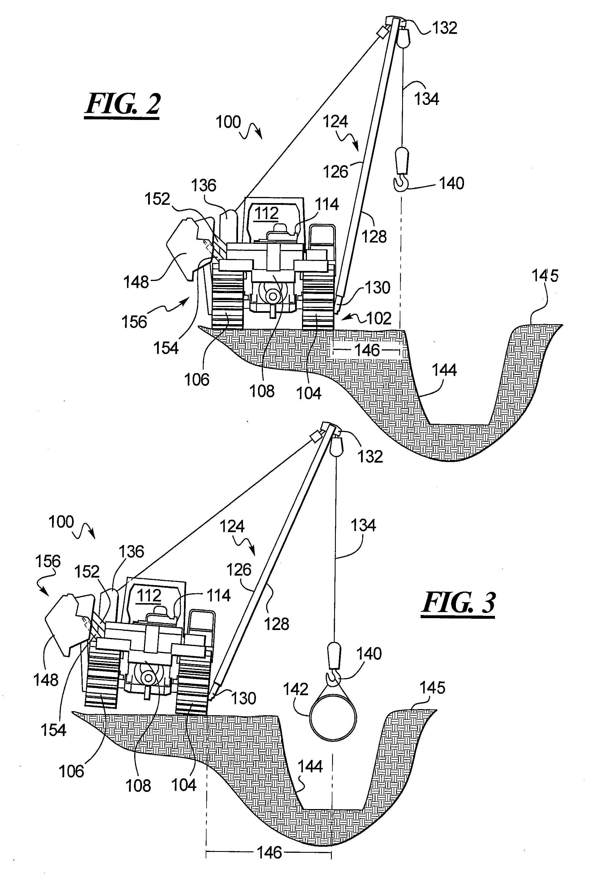
As the chassis, engine and undercarriage comprise the majority of the weight of a pipelayer, depending on the weight of the pipe being lifted and the length of the boom arm, the pipelayer can be subject to potential tipping and instability.
Conversely, if the pipelayer is to be maintained in a stable position, the ability of the pipelayer to access the desired installation location can be significantly limited.
The counterweight may comprise a series of heavy plates secured to a hinged structure such that through the use of a hydraulic cylinder or the like, the counterweight can be swung away from the chassis of the pipelayer on the side of the pipelayer opposite to the boom and thus counterbalance the weight of the load being lifted.
The lifting capacity and possible boom angle are therefore largely limited by such a fixed system.
The pipelayer could in theory simply be made larger and heavier to satisfy these needs, but realistically the general footprint of the pipelayer is limited by cost, maneuverability, and transportation considerations.
As stated above, pipelayers need to be operated in very remote and difficult locations.
Once built, they need to be sent by rail and / or truck for use, and thus the size of those rails and trucks limit the upper end in terms of dimensions of overall pipelayer design.
Even if they could be shipped to the location, they also have to be nimble enough to perform the job.
Moreover, over-sizing the undercarriage and boom of the pipelayer will also increase manufacturing costs in terms of materials, and operating costs in terms of fuel.

Method used


Image

  • Lightweight High-Performance Pipelayer
  • Lightweight High-Performance Pipelayer
  • Lightweight High-Performance Pipelayer

Examples


Embodiment Construction

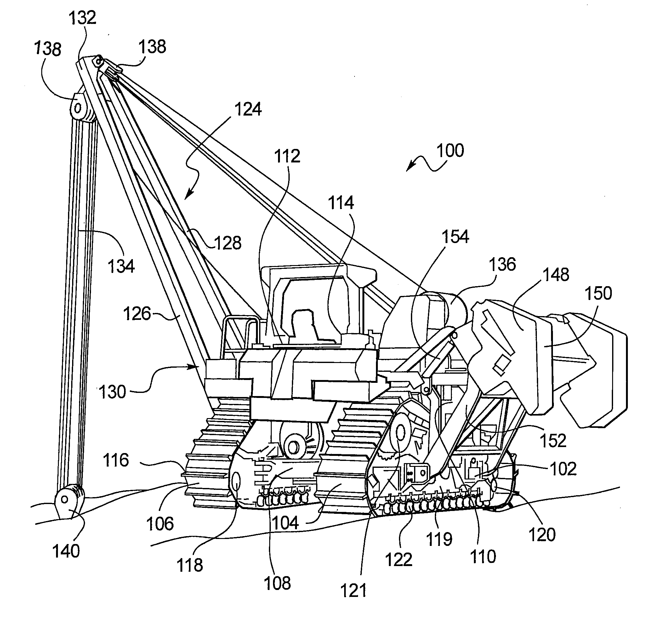
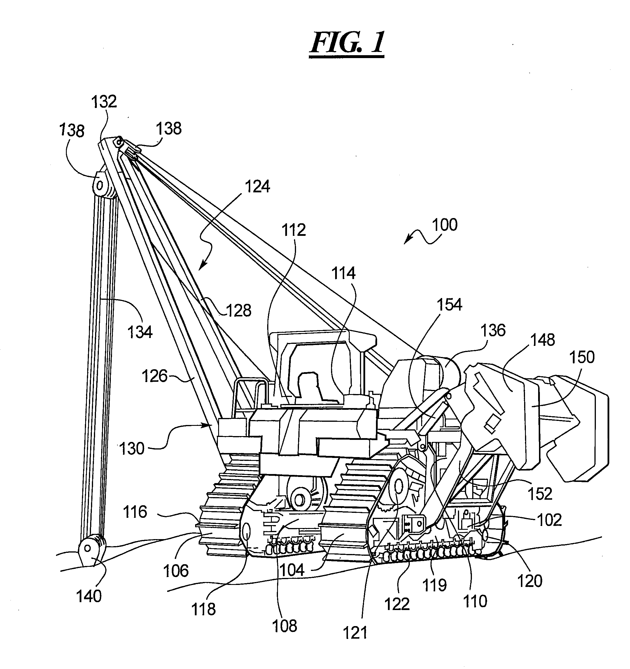
[0024]Referring now to the drawings, and with specific reference to FIG. 1, a pipelayer constructed in accordance with the present disclosure is generally referred to by reference numeral 100. While the following detailed description and drawings are made with reference to a pipelayer, it is important to note that the teachings of this disclosure can be employed on other earth moving or construction machines including, but not limited to, loaders, back-hoes, lift-trucks, cherry-pickers, forklifts, excavators, or any other movable vehicle where a load is being lifted at a distance from the main body of the vehicle.

[0025]The pipelayer 100 may include an undercarriage 102 comprised of first and second drive tracks 104, 106 supporting a chassis 108. A power source, typically a diesel engine, 110 is supported by the chassis 108. An operator seat 112 and control console 114 may also be supported by the chassis 108 from which the operator can control one or both tracks 104 and 106 to drive...


PUM


Abstract

A pipelayer providing higher lifting capacities without adding weight or size to an undercarriage or boom of the pipelayer is disclosed. The pipelayer is designed and sized to have a maximum lifting capacity when the boom is extended from the undercarriage a predetermined, relatively short distance. However, in use the boom often needs to extend further away from the undercarriage, and in so doing the lifting capacity of the pipelayer decreases. The present disclosure provides additional lifting capacity in that extended range by selectively deploying a counterweight away from the undercarriage once the boom is extended past the predetermined distance. In so doing, not only is the lifting capacity of the pipelayer increased, but the size and weight of the undercarriage and boom are not increased. This enables standard sized undercarriages and other supporting structure to be used, thereby aiding in maneuverability and shipping of the pipelayers, while at the same time reducing manufacturing and usage costs.

Description

CROSS-REFERENCE TO RELATED APPLICATION[0001]This is a non-provisional application claiming priority under 35 USC §119 (e) to U.S. Provisional Patent Application No. 61 / 249,828 filed on Oct. 8, 2009.TECHNICAL FIELD[0002]The present disclosure generally relates to construction vehicles and, more particularly, relates to pipelayers.BACKGROUND[0003]Pipelayers are specialized vehicles used for installing large, heavy lengths of conduit into or above ground. Such conduits may be used, for example, to carry oil and gas from remote well locations over vast distances to a receiving station or refinery. In so doing, transportation costs for shipping, trucking or otherwise moving the oil and gas can be avoided. In addition to petroleum pipelines, pipelayers can also be used to install piping for other materials, or for installing of drain tile, culverts or other irrigation and drainage structure.[0004]However, the installation of such pipelines is often very challenging. The locations of such ...

Claims


Application Information

Patent Timeline
IPC IPC(8): B66C23/76B66C23/88B66C13/16B66C23/36B66C13/18
CPCB66C23/76B66C23/44
Inventor CAMACHO, TIMOTHY E.GERBICK, KORY D.KLEIN, KEVIN J.SMITH, KENT D.WHITEHEAD, JONATHAN R.
Owner CATERPILLAR INC
Learn More